

Our Services
Compare Aerial LiDAR and Photogrammetry for Terrain Mapping
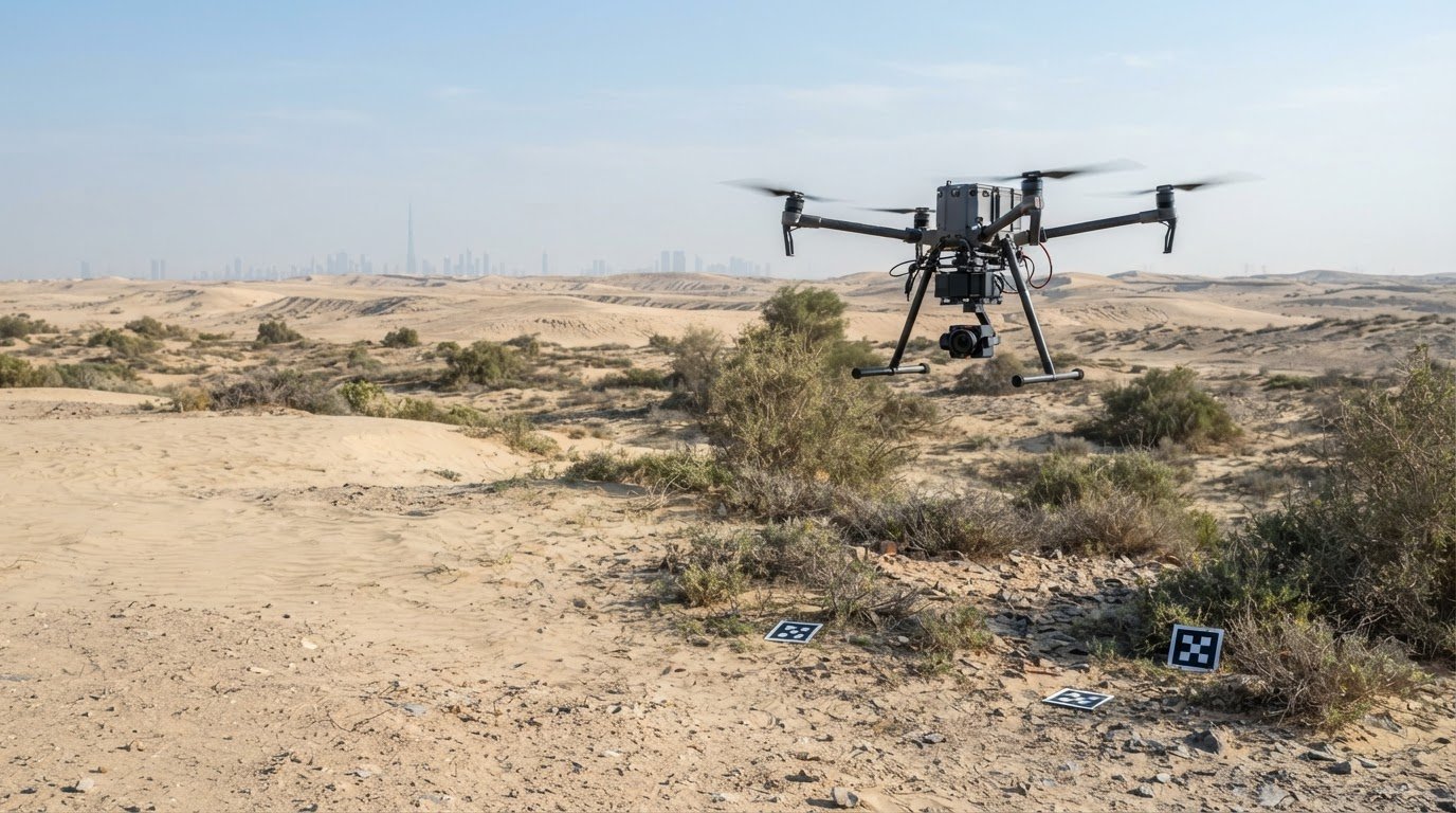
For terrain mapping, aerial LiDAR is often the stronger option when vegetation or dependable ground elevations are the main challenge. Photogrammetry suits open, cleared sites where detailed imagery and textured models matter. Choosing aerial LiDAR vs photogrammetry for terrain mapping depends on what the surface conceals and what the final model must show. Some projects benefit from combining both methods to capture elevation detail alongside colour and texture.
Both methods can produce useful terrain data, but they capture it differently. LiDAR measures reflected laser pulses, while photogrammetry reconstructs surfaces from overlapping photographs. Vegetation, lighting, and surface texture therefore affect each method in different ways.
This guide compares how each method captures terrain, handles vegetation, reconstructs images, and produces and classifies point clouds. It also explains when each approach suits projects in Dubai and across the UAE, helping you match the survey method to site conditions and intended use.
Key Takeaways
- Choose the capture method around site conditions and the terrain detail your project needs, rather than assuming one approach is always better.
- Consider LiDAR where vegetation may obscure ground levels; photogrammetry is often a strong fit for exposed, clearly visible surfaces.
- Understand how image overlap and site conditions influence photogrammetric terrain reconstruction and the outputs it can support.
- Compare point-cloud density alongside classification needs, colour, and texture before deciding which deliverables will serve your workflow.
- For projects that need both detailed elevation data and realistic visual context, assess whether combining the methods would provide a more complete terrain view.
What’s better, LIDAR or photogrammetry?
Neither method is universally better. Vegetation, terrain, environmental conditions, and deliverables all shape the choice. Compare how each captures ground elevations and how the data will support your project in Dubai or elsewhere in the UAE.
Accuracy in Vegetation and Complex Terrain
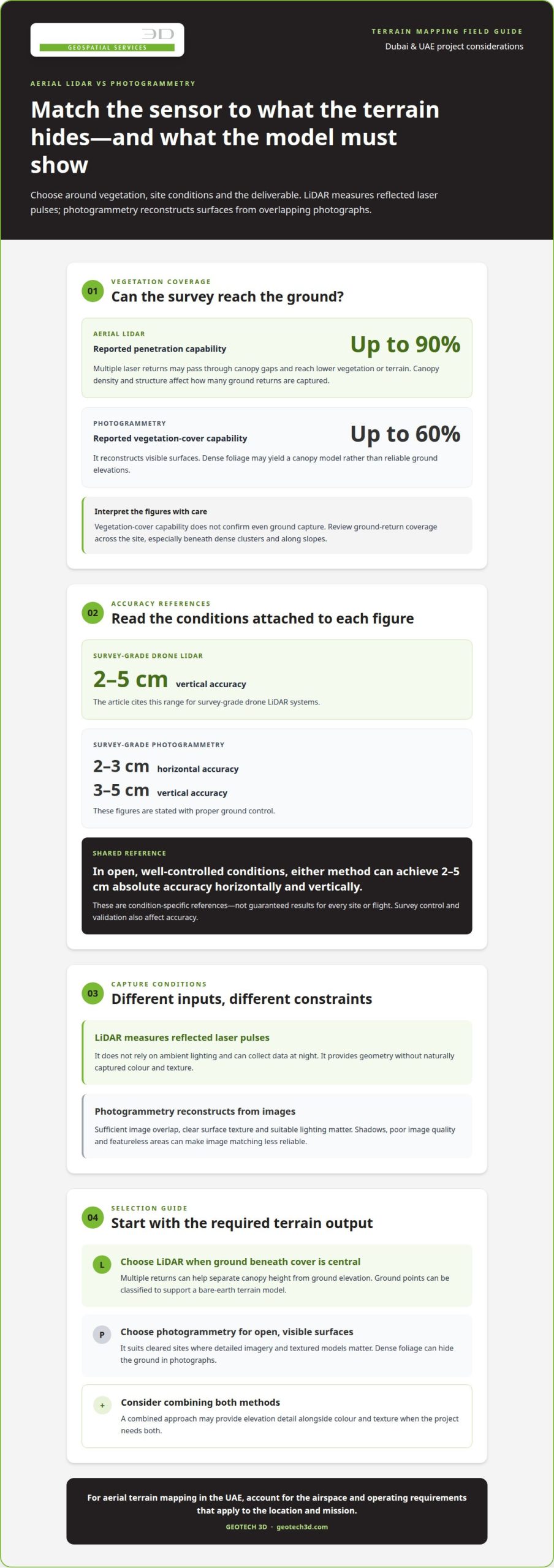
LiDAR can measure ground beneath vegetation because multiple laser returns may reach the terrain through canopy gaps. Photogrammetry reconstructs visible surfaces, so dense foliage may yield a canopy model rather than reliable ground elevations. LiDAR can provide useful elevation data on steep or sharply changing terrain, while image-based mapping suits clear, exposed ground.
Choose based on the target: ground beneath cover or visible surface detail. On a partly vegetated site, identify where the canopy may hide ground features before selecting a capture method.
Accuracy Across Environmental Conditions
Photogrammetry requires sufficient image overlap, clear surface texture, and suitable lighting. Shadows, poor image quality, and featureless areas can make image matching less reliable. LiDAR measures reflected laser pulses and does not rely on ambient lighting, so it can collect data at night. Site conditions still affect planning and the usefulness of either dataset.
For example, low-texture ground can challenge image matching in a way it does not challenge laser measurement. Consider these conditions alongside the intended model and survey purpose.
Survey Accuracy and Georeferencing
Accuracy depends on survey control and validation as well as the sensor. With proper ground control, survey-grade photogrammetry can achieve horizontal accuracy of 2-3 cm and vertical accuracy of 3-5 cm. In open, well-controlled conditions, aerial LiDAR and photogrammetry can achieve absolute accuracies of 2-5 cm horizontally and vertically.
Use control and independent checks to assess whether mapped positions and elevations are suitable for the construction task, such as reviewing earthworks or designing terrain.
Horizontal and Vertical Accuracy
Horizontal accuracy describes how closely mapped features align in plan. Vertical accuracy describes how closely measured elevations represent the ground. Survey-grade drone LiDAR systems can achieve vertical accuracy of 2-5 cm. Survey-grade photogrammetry can achieve horizontal accuracy of 2-3 cm with proper ground control. These figures apply to their stated conditions, not automatically to every site or flight.
As an external, broad-scale reference rather than a UAE project specification, the National Elevation Dataset, largely created using photogrammetric techniques, had accuracy on the order of 3 meters (10 feet) and 10- to 30-meter resolution, according to the National Oceanic and Atmospheric Administration (NOAA).
For aerial terrain mapping in the UAE, account for the airspace and operating requirements that apply to the location and mission. The relevant steps depend on the site and operation, so sensor selection alone does not establish compliance.
The limitations differ: LiDAR provides geometry without naturally captured colour and texture, while photogrammetry depends on image quality, lighting, and visible surface features. Dense vegetation can obscure terrain in photographs.
| Option | Vegetation and terrain | Environmental conditions | Accuracy reference |
|---|---|---|---|
| LiDAR | Can capture ground through canopy gaps | Independent of ambient lighting | 2-5 cm vertical accuracy for survey-grade drone systems |
| Photogrammetry | Well suited to exposed, visible surfaces | Image quality, lighting, and texture matter | 2-3 cm horizontal and 3-5 cm vertical with proper ground control |
Choose LiDAR when vegetation or ground elevation is central; choose photogrammetry when open surfaces and image detail matter.
Vegetation penetration
Vegetation affects what a terrain survey measures: the canopy surface and the ground below it are different targets. LiDAR can use multiple laser returns to capture ground elevations through vegetation, while photogrammetry reconstructs the surfaces visible in its images.
Canopy Penetration and Laser Measurement
Aerial LiDAR sends laser pulses toward the ground and records the reflected returns. Some pulses reflect from leaves or branches; others pass through gaps and return from lower vegetation or terrain. Multiple returns help separate canopy height from ground elevation in the point cloud.
Reported capabilities place LiDAR penetration at up to 90% vegetation cover, but canopy density and structure affect how many ground returns are captured. That makes LiDAR more suitable than image-based capture where vegetation obscures the terrain being surveyed.
For a practical assessment, distinguish canopy measurements from ground measurements in the required output. A point cloud with abundant vegetation returns does not, by itself, show that the underlying terrain has been captured evenly. Review ground-return coverage across the site, especially beneath dense clusters and along slopes.
Bare-Earth Terrain Models
A bare-earth terrain model represents the ground, not trees, shrubs, or other objects above it. LiDAR data can support this output because vegetation and ground returns can be classified separately, then points identified as ground can be used to build the terrain surface.
Photogrammetry generally maps the visible canopy where foliage blocks the ground. It is reported as able to capture up to 60% vegetation cover, but that does not mean it can consistently derive bare-earth elevations beneath dense cover.
Model quality depends on more than selecting LiDAR. Classification must distinguish ground points from low vegetation, structures, and other returns. On a vegetated slope, for example, incorrect classification can leave canopy points in the terrain model or remove genuine ground points. Inspecting the classified cloud against representative areas helps reveal errors before using the model for terrain analysis.
Ground-Surface Mapping Through Vegetation
For terrain mapping, the key question is whether the required surface is the vegetation canopy or the ground below it. LiDAR’s multiple returns can support both measurements; photogrammetric imagery mainly reconstructs surfaces visible to the camera. Dense foliage can therefore conceal ground breaks, drainage features, and slope changes.
On partially covered land, the methods can contribute different information. Photogrammetry can describe exposed ground with image texture, while LiDAR can add elevation observations beneath vegetation. Combining datasets can help represent visible surface detail and underlying terrain in one mapping workflow.
Before capture, define whether the deliverable needs canopy heights, bare-earth elevations, or both. Identify where vegetation is dense, where ground is exposed, and which areas need closer review. This helps teams interpret horizontal coverage and elevation data in context, rather than treating a visually complete surface as proof that the ground has been measured.
For example, on a construction site with scrub along its boundary, exposed work areas may be mapped from visible surfaces, while the vegetated edge needs ground-return assessment. This distinction informs how terrain models are interpreted and where gaps could affect design or earthworks decisions.
How photogrammetry reconstructs terrain from overlapping images
Photogrammetry converts aerial photographs into mapped surfaces by matching visible features across images. For drone surveys, sufficient overlap and consistent image quality help software calculate terrain shape and elevation.
Reconstruction from Aerial Images
The process begins with photographs of the same ground features from different camera positions. Software matches those features and uses triangulation to calculate their spatial relationships and depth. Repeated matches create a three-dimensional representation of the photographed surface, rather than a direct laser measurement.
Flight planning supports that reconstruction. A drone captures images along parallel flight lines, with enough front and side overlap for shared features to appear in neighbouring photographs. A survey-grade camera can achieve a ground sample distance of 1-2 cm per pixel at typical survey altitudes.
Processing can produce orthomosaics, digital surface models, textured 3D meshes, and dense point clouds. Each output serves a different purpose: an orthomosaic supports visual inspection, while a surface model represents elevations across the captured area.
Image Overlap and Processing
Overlap gives the software repeated views needed to match features and calculate depth. Photogrammetric drone surveys typically use 75-80% front overlap and 65-70% side overlap. Aerial photogrammetry commonly uses approximately 70-90% overlap between adjacent images, while images need at least 50% overlap to work well.
Lighting and texture affect image-matching quality. Good lighting, minimal shadows, and a consistent surface help software identify the same features across photographs. Dense vegetation, water, or featureless ground can make matching difficult because there are few distinct, stable image details.
Processing demand grows with the image set and required detail. A 100-hectare site flown at 2 cm GSD can produce 3,000-5,000 images. Processing may take several hours to over a day, depending on dataset size and the detail required.
Before a flight, plan overlap for the terrain and intended deliverables. After capture, review image coverage and quality, then process the aligned photographs into the required model. For a construction site, match the output to its purpose: an orthomosaic shows visible conditions, while a digital surface model supports elevation review.
Point-cloud density and classification
Point density describes how many measured points represent a surface area. Survey-grade drone LiDAR systems can capture 100-500+ points per square metre, creating detailed geometric point clouds. That density can help represent terrain features, but it doesn’t alone establish accuracy. The intended model, classification requirements, and distribution of points across the site also matter.
LiDAR, or light detection and ranging, measures reflected laser pulses to record surface geometry. Its sensor can collect data independently of ambient lighting, including at night. This is an operational advantage when daylight is unavailable, while photogrammetry relies on photographs and therefore on suitable image conditions.
Classification makes a raw LiDAR point cloud interpretable. Processing assigns points to categories such as ground, vegetation, or structures, supporting outputs such as classified clouds, digital terrain models, digital elevation models, and canopy height models. For terrain work, the ground class is especially important: a model built from ground points answers a different question from one representing canopy or buildings.
Photogrammetry provides a different balance of geometry and visual context. Overlapping images can produce dense point clouds, orthomosaics, digital surface models, and textured 3D meshes. The resulting points can carry colour and texture information captured in the photographs, which helps users understand visible site features alongside elevation.
LiDAR point clouds capture geometry but do not naturally include the colour and texture recorded by photogrammetry. Combining LiDAR data with RGB imagery can add colour and visual context to a laser-derived model. This can help when a project needs measured shape and a more recognisable view of features across the mapped surface.
Compare deliverables with the task, not just points per square metre. Earthworks review, for example, may need a classified ground surface, while site interpretation may benefit from an orthomosaic and textured mesh. A high-density cloud without the required classes may be less useful than data structured for the project’s specific terrain analysis.
Use a practical review sequence: identify the required output, assess whether colour or texture matters, then check point density and classification. For LiDAR, examine ground and vegetation classes separately. For photogrammetry, consider whether the image-derived cloud and orthomosaic show the required features. This comparison clarifies how each capture method supports construction planning or terrain assessment.
How aerial LiDAR and photogrammetry capture terrain
According to the National Oceanic and Atmospheric Administration (NOAA), airborne LiDAR uses a laser, scanner, and specialized GPS receiver; photogrammetry uses cameras. Drones or aircraft carry either method; photogrammetry can also use satellites, with ground control supporting georeferencing.
Sensors and Aircraft
LiDAR measures distance by emitting laser pulses and calculating their return time. The sensor records those measurements alongside positioning data to build a three-dimensional representation of terrain. Photogrammetry instead captures overlapping photographs, then uses software to match image features and reconstruct elevations.
Both sensors can be carried by aerial platforms, including drones and aircraft. Photogrammetry can also use satellite imagery for broad-area mapping, while drone cameras can capture detailed site imagery. The right platform depends on coverage, required resolution, and the terrain information needed.
These methods produce different source data. LiDAR starts with measured distances; photogrammetry starts with images and visual texture. Combining them can pair shape and elevation information with colour and surface detail, creating a richer terrain model than either dataset alone.
Ground Control
Ground control connects captured data to known ground positions. In photogrammetry, surveyed control points help georeference the reconstructed model, while separate check points can verify and document achieved accuracy. Control supports the model’s positioning; independent checks assess how well it matches surveyed locations.
For LiDAR, positioning information from the system’s specialized GPS receiver helps locate laser returns. Ground checks can assess the resulting terrain data against known points. In either workflow, a consistent coordinate reference is essential when survey outputs must align with design files or other project datasets.
Plan control around the area and intended use. For example, a Dubai construction site may need terrain data aligned with existing survey information before earthworks comparisons. Establish the project coordinate reference, distribute control across the mapped area, and reserve check points for validation. These steps make the capture workflow easier to assess and integrate.
Match the flight plan and sensor to the deliverable: elevation surfaces, visual imagery, or both. Then process the source data, review georeferencing, and assess coverage and classification before using the model for design decisions. The takeaway is simple: sensors record terrain differently, but flight planning, control, and processing determine whether the resulting information fits the project.
GEOTECH 3D: topo survey
GEOTECH 3D offers topo surveys to support terrain decisions for construction, site planning, and earthworks. Turn to this service when your project needs a mapped representation of existing ground conditions, or when you need survey information to guide design and site coordination.
Where aerial capture suits the site, GEOTECH 3D’s Drone Services can support data acquisition. GIS & Surveying Services can help place survey information within a broader spatial workflow. The appropriate method depends on the terrain, vegetation, required outputs, and how the resulting data will be used.
To discuss a terrain mapping requirement in Dubai or elsewhere in the UAE, contact GEOTECH 3D through its website.
Turn Your Terrain Data Into a Clear Project Decision
Let the intended use guide your next step. Before planning a survey, define how terrain data will support design, construction coordination, or site assessment. A concise project brief can identify the area to map, the decisions the data must support, and the deliverables your team needs.
That context makes choosing aerial LiDAR vs photogrammetry for terrain mapping more practical: the capture method should serve the work that follows, not just produce an impressive model. GEOTECH 3D offers topo surveys and Drone Services for terrain data acquisition, alongside 3D Laser Scanning for capturing physical site conditions where detailed spatial records are needed.
Share your site requirements and intended use with GEOTECH 3D to discuss a suitable surveying approach for your project in Dubai or elsewhere in the UAE.
A clear data plan gives your team a stronger foundation for the decisions ahead.
Frequently Asked Questions
Can one drone carry both a camera and a LiDAR sensor?
Yes, if the aircraft can safely accommodate the combined payload and the sensors can be integrated for the mission. Planning should account for how each sensor is mounted, how their positions relate, and whether their captures can be aligned during processing. A combined setup can help when the deliverable requires complementary datasets. Payload compatibility and the intended flight plan shape the practical choice.
Can photogrammetry see through trees?
No. If tree cover blocks the camera’s view, photographs cannot directly show the hidden ground. On a site with tree-covered areas, treat visible canopy and underlying terrain as separate information needs. If the ground itself must be represented, plan capture and verification suited to that requirement, rather than assuming an image-based model has recorded terrain beneath foliage.
What about cost?
LiDAR equipment is generally more expensive than photogrammetry equipment, but project cost also reflects the work needed to produce usable data. Price depends on the case and is provided after a quote request; factors include site area, access, vegetation, control requirements, processing, and deliverables. Compare equivalent scopes, including what data will be classified, checked, and prepared for the project team.
What accuracy can you expect from a drone survey?
Set expected accuracy against the decisions the survey will inform. For a design handover, define acceptable horizontal and elevation deviations separately, then identify how the survey will be checked against independent points. Earthworks tracking may need different acceptance criteria from detailed set-out support. Clear tolerances, a stated coordinate reference, and a documented validation method make the final accuracy easier to interpret.
What do you get at the end?
The final handover should include agreed data products and enough information for the receiving team to use them correctly. Specify the coordinate reference, file formats, survey date, and any classification or processing notes in the project requirements. A consultant integrating terrain data into design software, for example, needs consistent positioning and clear surface definitions. Agreeing these details early reduces ambiguity during review and reuse.
Which technology should you choose?
Start by recording the decision the survey must support, such as comparing existing ground with a design or documenting visible site conditions. Next, identify access constraints, vegetation, and the teams that will use the deliverables. If the project needs both visual context and terrain measurement, assess whether separate or combined datasets suit the workflow. This brief gives the survey method a practical basis.
How does aerial LiDAR compare with photogrammetry for terrain mapping?
When comparing aerial LiDAR vs photogrammetry for terrain mapping, consider what evidence each dataset provides to downstream users. A project team reviewing visible site conditions may value an image-based record, while terrain analysis may require structured elevation information. This also affects how users inspect and interpret the outputs. Define the intended decisions and handover requirements first, then assess which dataset best supports them.
What terrain mapping accuracy can aerial LiDAR and photogrammetry achieve?
Achievable accuracy is project-specific, not simply a sensor label. Specify the required horizontal and vertical tolerances, the coordinate reference, and the method for independent validation before capture. Review check-point residuals and coverage across representative parts of the site, including areas with different terrain or surface conditions. This gives the project team evidence to judge whether the delivered survey meets its intended use.
For terrain mapping, aerial LiDAR is often the stronger option when vegetation or dependable ground elevations are the main challenge. Photogrammetry suits open, cleared sites where detailed imagery and textured models matter. Choosing aerial LiDAR vs photogrammetry for terrain mapping depends on what the surface conceals and what the final model must show. Some projects benefit from combining both methods to capture elevation detail alongside colour and texture.
Both methods can produce useful terrain data, but they capture it differently. LiDAR measures reflected laser pulses, while photogrammetry reconstructs surfaces from overlapping photographs. Vegetation, lighting, and surface texture therefore affect each method in different ways.
This guide compares how each method captures terrain, handles vegetation, reconstructs images, and produces and classifies point clouds. It also explains when each approach suits projects in Dubai and across the UAE, helping you match the survey method to site conditions and intended use.
Key Takeaways
- Choose the capture method around site conditions and the terrain detail your project needs, rather than assuming one approach is always better.
- Consider LiDAR where vegetation may obscure ground levels; photogrammetry is often a strong fit for exposed, clearly visible surfaces.
- Understand how image overlap and site conditions influence photogrammetric terrain reconstruction and the outputs it can support.
- Compare point-cloud density alongside classification needs, colour, and texture before deciding which deliverables will serve your workflow.
- For projects that need both detailed elevation data and realistic visual context, assess whether combining the methods would provide a more complete terrain view.
What’s better, LIDAR or photogrammetry?
Neither method is universally better. Vegetation, terrain, environmental conditions, and deliverables all shape the choice. Compare how each captures ground elevations and how the data will support your project in Dubai or elsewhere in the UAE.
Accuracy in Vegetation and Complex Terrain
LiDAR can measure ground beneath vegetation because multiple laser returns may reach the terrain through canopy gaps. Photogrammetry reconstructs visible surfaces, so dense foliage may yield a canopy model rather than reliable ground elevations. LiDAR can provide useful elevation data on steep or sharply changing terrain, while image-based mapping suits clear, exposed ground.
Choose based on the target: ground beneath cover or visible surface detail. On a partly vegetated site, identify where the canopy may hide ground features before selecting a capture method.
Accuracy Across Environmental Conditions
Photogrammetry requires sufficient image overlap, clear surface texture, and suitable lighting. Shadows, poor image quality, and featureless areas can make image matching less reliable. LiDAR measures reflected laser pulses and does not rely on ambient lighting, so it can collect data at night. Site conditions still affect planning and the usefulness of either dataset.
For example, low-texture ground can challenge image matching in a way it does not challenge laser measurement. Consider these conditions alongside the intended model and survey purpose.
Survey Accuracy and Georeferencing
Accuracy depends on survey control and validation as well as the sensor. With proper ground control, survey-grade photogrammetry can achieve horizontal accuracy of 2-3 cm and vertical accuracy of 3-5 cm. In open, well-controlled conditions, aerial LiDAR and photogrammetry can achieve absolute accuracies of 2-5 cm horizontally and vertically.
Use control and independent checks to assess whether mapped positions and elevations are suitable for the construction task, such as reviewing earthworks or designing terrain.
Horizontal and Vertical Accuracy
Horizontal accuracy describes how closely mapped features align in plan. Vertical accuracy describes how closely measured elevations represent the ground. Survey-grade drone LiDAR systems can achieve vertical accuracy of 2-5 cm. Survey-grade photogrammetry can achieve horizontal accuracy of 2-3 cm with proper ground control. These figures apply to their stated conditions, not automatically to every site or flight.
As an external, broad-scale reference rather than a UAE project specification, the National Elevation Dataset, largely created using photogrammetric techniques, had accuracy on the order of 3 meters (10 feet) and 10- to 30-meter resolution, according to the National Oceanic and Atmospheric Administration (NOAA).
For aerial terrain mapping in the UAE, account for the airspace and operating requirements that apply to the location and mission. The relevant steps depend on the site and operation, so sensor selection alone does not establish compliance.
The limitations differ: LiDAR provides geometry without naturally captured colour and texture, while photogrammetry depends on image quality, lighting, and visible surface features. Dense vegetation can obscure terrain in photographs.
| Option | Vegetation and terrain | Environmental conditions | Accuracy reference |
|---|---|---|---|
| LiDAR | Can capture ground through canopy gaps | Independent of ambient lighting | 2-5 cm vertical accuracy for survey-grade drone systems |
| Photogrammetry | Well suited to exposed, visible surfaces | Image quality, lighting, and texture matter | 2-3 cm horizontal and 3-5 cm vertical with proper ground control |
Choose LiDAR when vegetation or ground elevation is central; choose photogrammetry when open surfaces and image detail matter.
Vegetation penetration
Vegetation affects what a terrain survey measures: the canopy surface and the ground below it are different targets. LiDAR can use multiple laser returns to capture ground elevations through vegetation, while photogrammetry reconstructs the surfaces visible in its images.
Canopy Penetration and Laser Measurement
Aerial LiDAR sends laser pulses toward the ground and records the reflected returns. Some pulses reflect from leaves or branches; others pass through gaps and return from lower vegetation or terrain. Multiple returns help separate canopy height from ground elevation in the point cloud.
Reported capabilities place LiDAR penetration at up to 90% vegetation cover, but canopy density and structure affect how many ground returns are captured. That makes LiDAR more suitable than image-based capture where vegetation obscures the terrain being surveyed.
For a practical assessment, distinguish canopy measurements from ground measurements in the required output. A point cloud with abundant vegetation returns does not, by itself, show that the underlying terrain has been captured evenly. Review ground-return coverage across the site, especially beneath dense clusters and along slopes.
Bare-Earth Terrain Models
A bare-earth terrain model represents the ground, not trees, shrubs, or other objects above it. LiDAR data can support this output because vegetation and ground returns can be classified separately, then points identified as ground can be used to build the terrain surface.
Photogrammetry generally maps the visible canopy where foliage blocks the ground. It is reported as able to capture up to 60% vegetation cover, but that does not mean it can consistently derive bare-earth elevations beneath dense cover.
Model quality depends on more than selecting LiDAR. Classification must distinguish ground points from low vegetation, structures, and other returns. On a vegetated slope, for example, incorrect classification can leave canopy points in the terrain model or remove genuine ground points. Inspecting the classified cloud against representative areas helps reveal errors before using the model for terrain analysis.
Ground-Surface Mapping Through Vegetation
For terrain mapping, the key question is whether the required surface is the vegetation canopy or the ground below it. LiDAR’s multiple returns can support both measurements; photogrammetric imagery mainly reconstructs surfaces visible to the camera. Dense foliage can therefore conceal ground breaks, drainage features, and slope changes.
On partially covered land, the methods can contribute different information. Photogrammetry can describe exposed ground with image texture, while LiDAR can add elevation observations beneath vegetation. Combining datasets can help represent visible surface detail and underlying terrain in one mapping workflow.
Before capture, define whether the deliverable needs canopy heights, bare-earth elevations, or both. Identify where vegetation is dense, where ground is exposed, and which areas need closer review. This helps teams interpret horizontal coverage and elevation data in context, rather than treating a visually complete surface as proof that the ground has been measured.
For example, on a construction site with scrub along its boundary, exposed work areas may be mapped from visible surfaces, while the vegetated edge needs ground-return assessment. This distinction informs how terrain models are interpreted and where gaps could affect design or earthworks decisions.
How photogrammetry reconstructs terrain from overlapping images
Photogrammetry converts aerial photographs into mapped surfaces by matching visible features across images. For drone surveys, sufficient overlap and consistent image quality help software calculate terrain shape and elevation.
Reconstruction from Aerial Images
The process begins with photographs of the same ground features from different camera positions. Software matches those features and uses triangulation to calculate their spatial relationships and depth. Repeated matches create a three-dimensional representation of the photographed surface, rather than a direct laser measurement.
Flight planning supports that reconstruction. A drone captures images along parallel flight lines, with enough front and side overlap for shared features to appear in neighbouring photographs. A survey-grade camera can achieve a ground sample distance of 1-2 cm per pixel at typical survey altitudes.
Processing can produce orthomosaics, digital surface models, textured 3D meshes, and dense point clouds. Each output serves a different purpose: an orthomosaic supports visual inspection, while a surface model represents elevations across the captured area.
Image Overlap and Processing
Overlap gives the software repeated views needed to match features and calculate depth. Photogrammetric drone surveys typically use 75-80% front overlap and 65-70% side overlap. Aerial photogrammetry commonly uses approximately 70-90% overlap between adjacent images, while images need at least 50% overlap to work well.
Lighting and texture affect image-matching quality. Good lighting, minimal shadows, and a consistent surface help software identify the same features across photographs. Dense vegetation, water, or featureless ground can make matching difficult because there are few distinct, stable image details.
Processing demand grows with the image set and required detail. A 100-hectare site flown at 2 cm GSD can produce 3,000-5,000 images. Processing may take several hours to over a day, depending on dataset size and the detail required.
Before a flight, plan overlap for the terrain and intended deliverables. After capture, review image coverage and quality, then process the aligned photographs into the required model. For a construction site, match the output to its purpose: an orthomosaic shows visible conditions, while a digital surface model supports elevation review.
Point-cloud density and classification
Point density describes how many measured points represent a surface area. Survey-grade drone LiDAR systems can capture 100-500+ points per square metre, creating detailed geometric point clouds. That density can help represent terrain features, but it doesn’t alone establish accuracy. The intended model, classification requirements, and distribution of points across the site also matter.
LiDAR, or light detection and ranging, measures reflected laser pulses to record surface geometry. Its sensor can collect data independently of ambient lighting, including at night. This is an operational advantage when daylight is unavailable, while photogrammetry relies on photographs and therefore on suitable image conditions.
Classification makes a raw LiDAR point cloud interpretable. Processing assigns points to categories such as ground, vegetation, or structures, supporting outputs such as classified clouds, digital terrain models, digital elevation models, and canopy height models. For terrain work, the ground class is especially important: a model built from ground points answers a different question from one representing canopy or buildings.
Photogrammetry provides a different balance of geometry and visual context. Overlapping images can produce dense point clouds, orthomosaics, digital surface models, and textured 3D meshes. The resulting points can carry colour and texture information captured in the photographs, which helps users understand visible site features alongside elevation.
LiDAR point clouds capture geometry but do not naturally include the colour and texture recorded by photogrammetry. Combining LiDAR data with RGB imagery can add colour and visual context to a laser-derived model. This can help when a project needs measured shape and a more recognisable view of features across the mapped surface.
Compare deliverables with the task, not just points per square metre. Earthworks review, for example, may need a classified ground surface, while site interpretation may benefit from an orthomosaic and textured mesh. A high-density cloud without the required classes may be less useful than data structured for the project’s specific terrain analysis.
Use a practical review sequence: identify the required output, assess whether colour or texture matters, then check point density and classification. For LiDAR, examine ground and vegetation classes separately. For photogrammetry, consider whether the image-derived cloud and orthomosaic show the required features. This comparison clarifies how each capture method supports construction planning or terrain assessment.
How aerial LiDAR and photogrammetry capture terrain
According to the National Oceanic and Atmospheric Administration (NOAA), airborne LiDAR uses a laser, scanner, and specialized GPS receiver; photogrammetry uses cameras. Drones or aircraft carry either method; photogrammetry can also use satellites, with ground control supporting georeferencing.
Sensors and Aircraft
LiDAR measures distance by emitting laser pulses and calculating their return time. The sensor records those measurements alongside positioning data to build a three-dimensional representation of terrain. Photogrammetry instead captures overlapping photographs, then uses software to match image features and reconstruct elevations.
Both sensors can be carried by aerial platforms, including drones and aircraft. Photogrammetry can also use satellite imagery for broad-area mapping, while drone cameras can capture detailed site imagery. The right platform depends on coverage, required resolution, and the terrain information needed.
These methods produce different source data. LiDAR starts with measured distances; photogrammetry starts with images and visual texture. Combining them can pair shape and elevation information with colour and surface detail, creating a richer terrain model than either dataset alone.
Ground Control
Ground control connects captured data to known ground positions. In photogrammetry, surveyed control points help georeference the reconstructed model, while separate check points can verify and document achieved accuracy. Control supports the model’s positioning; independent checks assess how well it matches surveyed locations.
For LiDAR, positioning information from the system’s specialized GPS receiver helps locate laser returns. Ground checks can assess the resulting terrain data against known points. In either workflow, a consistent coordinate reference is essential when survey outputs must align with design files or other project datasets.
Plan control around the area and intended use. For example, a Dubai construction site may need terrain data aligned with existing survey information before earthworks comparisons. Establish the project coordinate reference, distribute control across the mapped area, and reserve check points for validation. These steps make the capture workflow easier to assess and integrate.
Match the flight plan and sensor to the deliverable: elevation surfaces, visual imagery, or both. Then process the source data, review georeferencing, and assess coverage and classification before using the model for design decisions. The takeaway is simple: sensors record terrain differently, but flight planning, control, and processing determine whether the resulting information fits the project.
GEOTECH 3D: topo survey
GEOTECH 3D offers topo surveys to support terrain decisions for construction, site planning, and earthworks. Turn to this service when your project needs a mapped representation of existing ground conditions, or when you need survey information to guide design and site coordination.
Where aerial capture suits the site, GEOTECH 3D’s Drone Services can support data acquisition. GIS & Surveying Services can help place survey information within a broader spatial workflow. The appropriate method depends on the terrain, vegetation, required outputs, and how the resulting data will be used.
To discuss a terrain mapping requirement in Dubai or elsewhere in the UAE, contact GEOTECH 3D through its website.
Turn Your Terrain Data Into a Clear Project Decision
Let the intended use guide your next step. Before planning a survey, define how terrain data will support design, construction coordination, or site assessment. A concise project brief can identify the area to map, the decisions the data must support, and the deliverables your team needs.
That context makes choosing aerial LiDAR vs photogrammetry for terrain mapping more practical: the capture method should serve the work that follows, not just produce an impressive model. GEOTECH 3D offers topo surveys and Drone Services for terrain data acquisition, alongside 3D Laser Scanning for capturing physical site conditions where detailed spatial records are needed.
Share your site requirements and intended use with GEOTECH 3D to discuss a suitable surveying approach for your project in Dubai or elsewhere in the UAE.
A clear data plan gives your team a stronger foundation for the decisions ahead.
Frequently Asked Questions
Can one drone carry both a camera and a LiDAR sensor?
Yes, if the aircraft can safely accommodate the combined payload and the sensors can be integrated for the mission. Planning should account for how each sensor is mounted, how their positions relate, and whether their captures can be aligned during processing. A combined setup can help when the deliverable requires complementary datasets. Payload compatibility and the intended flight plan shape the practical choice.
Can photogrammetry see through trees?
No. If tree cover blocks the camera’s view, photographs cannot directly show the hidden ground. On a site with tree-covered areas, treat visible canopy and underlying terrain as separate information needs. If the ground itself must be represented, plan capture and verification suited to that requirement, rather than assuming an image-based model has recorded terrain beneath foliage.
What about cost?
LiDAR equipment is generally more expensive than photogrammetry equipment, but project cost also reflects the work needed to produce usable data. Price depends on the case and is provided after a quote request; factors include site area, access, vegetation, control requirements, processing, and deliverables. Compare equivalent scopes, including what data will be classified, checked, and prepared for the project team.
What accuracy can you expect from a drone survey?
Set expected accuracy against the decisions the survey will inform. For a design handover, define acceptable horizontal and elevation deviations separately, then identify how the survey will be checked against independent points. Earthworks tracking may need different acceptance criteria from detailed set-out support. Clear tolerances, a stated coordinate reference, and a documented validation method make the final accuracy easier to interpret.
What do you get at the end?
The final handover should include agreed data products and enough information for the receiving team to use them correctly. Specify the coordinate reference, file formats, survey date, and any classification or processing notes in the project requirements. A consultant integrating terrain data into design software, for example, needs consistent positioning and clear surface definitions. Agreeing these details early reduces ambiguity during review and reuse.
Which technology should you choose?
Start by recording the decision the survey must support, such as comparing existing ground with a design or documenting visible site conditions. Next, identify access constraints, vegetation, and the teams that will use the deliverables. If the project needs both visual context and terrain measurement, assess whether separate or combined datasets suit the workflow. This brief gives the survey method a practical basis.
How does aerial LiDAR compare with photogrammetry for terrain mapping?
When comparing aerial LiDAR vs photogrammetry for terrain mapping, consider what evidence each dataset provides to downstream users. A project team reviewing visible site conditions may value an image-based record, while terrain analysis may require structured elevation information. This also affects how users inspect and interpret the outputs. Define the intended decisions and handover requirements first, then assess which dataset best supports them.
What terrain mapping accuracy can aerial LiDAR and photogrammetry achieve?
Achievable accuracy is project-specific, not simply a sensor label. Specify the required horizontal and vertical tolerances, the coordinate reference, and the method for independent validation before capture. Review check-point residuals and coverage across representative parts of the site, including areas with different terrain or surface conditions. This gives the project team evidence to judge whether the delivered survey meets its intended use.
Search Now
Error: Contact form not found.