

Our Services
How to Avoid Construction Rework with 3D Scanning: A Practical Guide
What if the drawings match the design but the site no longer matches the drawings? In Dubai and across the UAE, that gap can become apparent after installation begins, when fixing a conflict may disrupt coordination and sequencing. Understanding how to avoid construction rework with 3D scanning starts with checking existing conditions before teams rely on assumptions.
Scanning can reveal differences, but collecting point-cloud data alone will not prevent rework. The information must be reviewed against suitable project references, and findings must reach the people responsible for decisions. A clear process turns measured conditions into timely coordination actions.
This guide explains when 3D scanning can help verify site conditions and how captured data can support design and construction coordination. You’ll learn how to define scan coverage and accuracy requirements, review discrepancies, and agree how to resolve them. We’ll also look at how 3D Scanning To BIM and Scan To CAD can connect site capture with project deliverables, helping teams make informed decisions before avoidable conflicts progress further.
How to avoid construction rework with 3D scanning
Start with the decision the project team needs to make, then identify the site conditions and references needed to inform it. Capture the relevant area, compare the data with current drawings or BIM, assign apparent discrepancies for professional review, and verify the agreed resolution. This process makes scanning part of coordination rather than a standalone data-collection task.
Key Takeaways
- Learn why corrective work happens and where scanning can help verify site conditions, without treating scan data as a complete solution on its own.
- Follow how to avoid construction rework with 3D scanning by turning captured conditions into reviewed, actionable coordination information.
- Understand how scanning, drawing reviews, targeted measurements, and BIM coordination can complement one another, while engineering review remains essential.
- Use a repeatable discrepancy process that records each issue’s location, reference, reviewer, responsible party, and status.
- See how GEOTECH 3D’s 3D Scanning To BIM, 3D Documentation, and Scan To CAD can be aligned with project requirements and deliverables.
Why construction rework happens, and where 3D scanning can help
Construction rework is corrective work required because installed or planned work conflicts with a discrepancy, omission, or misunderstood site condition. A drawing may show the design intent, while the actual building has changed, was documented incompletely, or contains elements in different positions than expected. If teams discover the difference after dependent work proceeds, they may need to revise details, coordinate a change, or redo completed work.
Reality capture records observable conditions; it does not approve a design or determine whether a proposed change is structurally or technically acceptable. 3D laser scanning measures visible surfaces to create a spatial record that teams can compare with project information. That record can inform a decision, but the appropriate consultant or engineer remains responsible for technical review and approval.
The practical value lies in checking relevant conditions early enough to inform coordination. Scanning contributes to how to avoid construction rework with 3D scanning only when findings reach the people who can resolve a discrepancy before affected work moves forward.
Which construction discrepancies are suitable for scan-based checking?
Scanning can help check visible geometry, installed elements, clearances, access constraints, and differences from documented existing conditions. For example, when planning a renovation interface, teams can compare a measured wall or opening with design information. In a congested building area, captured surfaces can help reviewers understand spatial relationships and identify where further coordination is needed.
Laser scanning records surfaces that are visible from scan positions. Concealed services, conditions inside walls, and other hidden elements require suitable investigation beyond visible scan data.
Why timing matters on Dubai and UAE projects
Verification is most useful when it informs sequencing, not after dependent work has made a discrepancy harder to address. Before installation or fit-out proceeds in an affected area, project teams can review the relevant scan information, clarify the apparent conflict, and agree who will assess and resolve it.
On projects in Dubai and across the UAE, contractors, consultants, engineers, and project managers may each hold different parts of the coordination picture. Sharing a clearly referenced site condition helps those teams discuss the same issue and determine the next action. Confirm project-specific documentation and approval requirements with the responsible parties instead of assuming one process applies to every project.
How 3D scanning turns site conditions into coordination evidence
A scan becomes useful through a defined process, not simply by collecting a large volume of data. The project team identifies the decision to inform, captures and processes relevant conditions, compares them with suitable references, assigns follow-up, and verifies the outcome. This gives field information a clear route into project coordination.
Scan data becomes useful when teams compare it with a defined reference. A point cloud is a measured representation of captured surfaces. It shows geometry recorded during scanning, but it is not automatically a design model, an approved deliverable, or confirmation that an installation complies with design intent.
Set the scan scope before mobilizing to site
Begin with the coordination question: what needs checking, where, and before which decision or activity? Define the area, project stage, relevant elements, access constraints, and the people who will review the findings. Plan safe access around site operations, then agree the required coverage, coordinate reference, accuracy requirements, deliverables, and handover format with project stakeholders.
Confirm whether the team needs a point cloud for review or modelled information for coordination. Where the scope calls for BIM-ready information, 3D Scanning To BIM can connect captured conditions to a model for comparison. Agree the required level of detail and intended model use for the project rather than assuming them.
Compare captured conditions with drawings or BIM
Comparison depends on suitable reference information and consistent project coordinates. Reviewers can align captured data with current drawings or a Building Information Model (BIM), then flag apparent deviations for investigation. A difference is a prompt for technical review, not automatically a defect. It may reflect a change, a tolerance, an outdated reference, or a genuine coordination issue.
For a project-specific discussion of 3D scanning and Scan To BIM, first clarify what the capture must support and how the findings will be reviewed. GEOTECH 3D provides 3D Scanning To BIM as one way to connect captured conditions with a BIM workflow.
Close the loop by recording the decision, assigning responsibility for action, and checking the relevant condition again when needed. This makes scanning part of a coordination process and supports how to avoid construction rework with 3D scanning without treating technology as a substitute for professional judgment.
3D scanning versus drawings, spot checks, and BIM coordination
Each verification method answers a different question. Drawings show documented design or existing information. Targeted measurements check specific dimensions. 3D scanning records visible surfaces across an agreed area, while BIM coordination helps teams review how modelled elements relate to one another. Choose the method according to the risk, area, and decision at hand rather than assuming one approach is always superior.
Drawings review: Useful for checking design information and identifying inconsistencies across documents. Drawings may not reflect current site conditions.
Targeted measurements: Useful for confirming a specific dimension or installation. They provide focused evidence, but not broad spatial context.
3D scanning: Useful for documenting visible geometry across a defined area. Findings are limited to captured surfaces and the agreed scan scope.
BIM coordination: Useful for reviewing relationships and potential conflicts between modelled elements. Its value depends on the quality and relevance of the models being compared.
These approaches can work together. A drawing review may identify an area that needs verification; a scan or targeted measurement can check the site; and BIM coordination may help assess model relationships. None replaces engineering review. The responsible professionals must interpret an apparent mismatch before deciding whether it requires a design change, further investigation, or another action.
When is a full scan more useful than targeted measurements?
A broader scan may suit complex geometry, dense interfaces, or renovation work where teams need spatial context across multiple visible elements. It can help reviewers understand how conditions relate beyond a single measurement point. A targeted check may be more proportionate when the question is narrow, such as confirming a particular opening or installation dimension. Confirm coverage and accuracy requirements with the responsible project professionals.
What a point cloud can, and cannot, confirm
A point cloud can support geometric review of visible surfaces captured within the agreed scope. By itself, it cannot establish design intent, reveal concealed conditions, or determine code compliance. Those questions require relevant documents, investigations, and professional assessments. For renovation work, define which visible conditions need to be documented and what decisions the record is intended to support.
To apply how to avoid construction rework with 3D scanning, match the capture method to the decision: define what must be checked, select suitable references, and involve the appropriate reviewers before work proceeds.
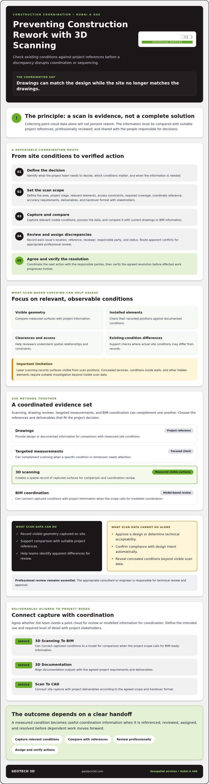
A practical workflow for using scan findings to prevent rework
A scan finding needs a clear route from observation to decision, action, and verification. Without assigned ownership and a recorded outcome, a discrepancy can remain visible in the data but unresolved in the field. Use the project’s established design, coordination, and quality processes to assess and approve any required change.
A repeatable workflow can keep the handoff clear:
- Plan: Define the area and decision to check, the required scan coverage and accuracy, and who will review the results.
- Capture and review: Record the relevant site conditions, then compare them with the agreed drawing, model, or other reference.
- Log and assign: Create an issue for each apparent discrepancy, identify the appropriate discipline for review, and set a responsible party and status.
- Resolve and verify: Record the decision, communicate any approved change before affected work proceeds, and confirm the outcome using the project’s agreed inspection or rescan method.
- Close out: Link the verification evidence and final status to the issue record and relevant project reference.
For each discrepancy, record its location, reference, reviewer, responsible party, and status. Add a clear description of what the scan shows, without presenting an initial observation as a confirmed design issue.
Turn a scan finding into an assigned coordination issue
Use distinct stages in the issue record. An observed condition describes what appears in the captured data; a suspected conflict identifies a possible mismatch that needs assessment; and a confirmed design issue reflects a conclusion reached through the project’s review process. Route each issue to the relevant consultant, engineer, or other responsible discipline. Record decisions and communicate potential impacts before dependent construction proceeds.
Verify the correction before closing the issue
Close an issue only after the project’s agreed inspection or rescan method confirms the outcome, not simply because a change was made. Keep the evidence connected to the drawing reference, model location, or coordination record so reviewers can trace what was checked and what decision followed.
Checklist: Locate the finding, link its reference, assign the right reviewer and responsible party, record the approved action, verify the result, and document closure.
This disciplined handoff is central to how to avoid construction rework with 3D scanning: scan evidence informs the process, while project professionals assess and approve the response.
For an overview of GEOTECH 3D’s scanning services and deliverables, explore the service information and consider how it fits the project’s review process.
How GEOTECH 3D can support a scan-led rework-prevention plan
For scanning to support construction coordination, the scope and deliverables need to match the decisions the project team must make. A clear brief establishes which conditions to capture, which references to use, and how the resulting information will be reviewed. This gives contractors, consultants, engineers, and project managers a practical basis for deciding how scan findings fit into their coordination process.
GEOTECH 3D provides 3D Scanning To BIM, 3D Documentation, and Scan To CAD. The appropriate deliverable depends on the project’s intended use. Where teams need BIM-ready information for design coordination, 3D Scanning To BIM can connect captured site conditions with that workflow. GEOTECH 3D’s Scan to BIM presentation lists indoor, outdoor, and over-ceiling data capture capabilities.
What to include in a Dubai project scanning brief
Give the scanning team enough context to understand the site and intended use. A brief for a project in Dubai or elsewhere in the UAE can identify:
- The project stage and the decision the scan should inform.
- The areas and elements to capture, along with known access constraints and safe-access considerations.
- Available reference information, such as relevant drawings or models.
- The intended use and requested deliverables, such as 3D Documentation, Scan To CAD, or 3D Scanning To BIM.
- Who will review the information, manage the handover, and act on any findings.
Ask relevant stakeholders to confirm the required coverage, accuracy, coordinate reference, and data format before finalising the scope. Agree how access will be coordinated with site operations and who will receive and review the handover. These project-specific decisions help ensure the capture is planned around a defined need, rather than collecting information without an agreed use.
Discussing scope and deliverables with GEOTECH 3D
If your team is considering 3D Scanning To BIM or Scan To CAD, bring the project brief, reference information, and intended use into the scope discussion. GEOTECH 3D serves construction and project management firms in Dubai and the UAE. Its stated solutions extend from raw point-cloud data to BIM-ready models compatible with client CAD packages. No scanning approach can guarantee that rework will be avoided, but a well-defined scope can help teams use captured information as part of their review and coordination process.
Understanding how to avoid construction rework with 3D scanning means connecting capture to project decisions, clear review responsibilities, and an agreed handover. GEOTECH 3D’s Dubai office is Ilyaa Tower 2 – Office 101, Damascus St., Al Qusais Industrial 3. Tel +971 4 295 1589.
To discuss project requirements and handover expectations, review GEOTECH 3D’s scanning information before defining the scope.
Make Site Verification Part of Your Coordination Plan
Reducing avoidable rework starts with checking the conditions that matter before dependent work proceeds. 3D scanning can document visible site geometry, but its value depends on comparing the data with suitable project references and routing findings through the right review and approval process.
A repeatable workflow helps teams move from scan capture to assigned action and verified closeout. Choose the capture scope according to the decision at hand, record each discrepancy clearly, and involve the responsible project professionals before making changes. That’s the practical foundation of how to avoid construction rework with 3D scanning.
GEOTECH 3D lists 3D Scanning To BIM, 3D Documentation, and Scan To CAD. Its Scan to BIM presentation identifies indoor, outdoor, and over-ceiling data capture. Discussing project requirements and handover expectations at the outset can help determine which deliverables suit your coordination needs.
With a clear brief and a disciplined review process, your team can make informed decisions from site data and coordinate next steps with confidence.
Frequently Asked Questions
How does 3D scanning help prevent construction rework?
To understand how to avoid construction rework with 3D scanning, use captured site conditions to check visible geometry against current drawings or BIM before dependent work proceeds. A point cloud can help teams identify apparent differences around openings, installed elements, or clearances. Reviewers must assess each finding, assign an action, and verify the outcome. Scanning itself does not approve changes or prevent every error.
At what stage should a construction project use 3D scanning?
Use 3D scanning when verifying existing or installed conditions can inform an upcoming project decision. This may be during renovation planning, before work depends on a particular interface, or later when the team needs to document visible conditions. Define the area and purpose first. The project team should agree on scan timing, access, coverage, and deliverables so the information is available for the relevant review.
Can a point cloud be compared directly with BIM?
A point cloud can be compared with BIM when the data and model are suitable for the intended review and use a consistent coordinate reference. The comparison may help reviewers assess relationships between captured surfaces and modelled elements. It does not automatically confirm that the model is current or that a detected difference is a defect. A qualified project reviewer should assess apparent deviations and determine the appropriate response.
Does 3D scanning replace site inspections or measurements?
No. 3D scanning, site inspections, and targeted measurements serve different purposes and can complement one another. A scan records visible surfaces within its agreed scope, while an inspection can assess conditions or workmanship that require direct observation. A targeted measurement may answer a specific dimensional question. Select the method according to the decision, required accuracy, and project process, and retain engineering review where technical judgment is needed.
What information should a contractor provide before requesting a 3D scan?
Provide the project stage, areas and elements to capture, access constraints, available drawings or models, intended use, and requested deliverables. Identify who will review the scan and receive the handover. Before agreeing the scope, ask stakeholders to confirm coverage, accuracy, coordinate reference, and data-format requirements. Include site-access and safety considerations so capture planning accounts for operational conditions and responsibilities.
Can 3D scanning detect hidden pipes or services?
Laser scanning captures visible surfaces; it cannot reveal pipes or services concealed inside walls, floors, or ceilings. A visible pipe may appear in the scan, but the point cloud does not establish the location of hidden assets. If subsurface or concealed utility information is required, the project team should identify an appropriate investigation method and define its scope separately.
How do project teams act on discrepancies found in a scan?
Record each finding with its location, relevant drawing or model reference, reviewer, responsible party, and status. Distinguish an observed condition from a suspected conflict, then route it to the appropriate project discipline for assessment. The responsible professionals should document and approve any change through established design and quality processes. Before closing the issue, verify the resolution using the inspection or rescan method agreed for the project.
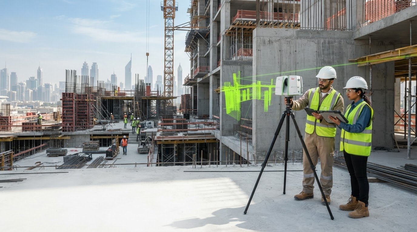
What if the drawings match the design but the site no longer matches the drawings? In Dubai and across the UAE, that gap can become apparent after installation begins, when fixing a conflict may disrupt coordination and sequencing. Understanding how to avoid construction rework with 3D scanning starts with checking existing conditions before teams rely on assumptions.
Scanning can reveal differences, but collecting point-cloud data alone will not prevent rework. The information must be reviewed against suitable project references, and findings must reach the people responsible for decisions. A clear process turns measured conditions into timely coordination actions.
This guide explains when 3D scanning can help verify site conditions and how captured data can support design and construction coordination. You’ll learn how to define scan coverage and accuracy requirements, review discrepancies, and agree how to resolve them. We’ll also look at how 3D Scanning To BIM and Scan To CAD can connect site capture with project deliverables, helping teams make informed decisions before avoidable conflicts progress further.
How to avoid construction rework with 3D scanning
Start with the decision the project team needs to make, then identify the site conditions and references needed to inform it. Capture the relevant area, compare the data with current drawings or BIM, assign apparent discrepancies for professional review, and verify the agreed resolution. This process makes scanning part of coordination rather than a standalone data-collection task.
Key Takeaways
- Learn why corrective work happens and where scanning can help verify site conditions, without treating scan data as a complete solution on its own.
- Follow how to avoid construction rework with 3D scanning by turning captured conditions into reviewed, actionable coordination information.
- Understand how scanning, drawing reviews, targeted measurements, and BIM coordination can complement one another, while engineering review remains essential.
- Use a repeatable discrepancy process that records each issue’s location, reference, reviewer, responsible party, and status.
- See how GEOTECH 3D’s 3D Scanning To BIM, 3D Documentation, and Scan To CAD can be aligned with project requirements and deliverables.
Why construction rework happens, and where 3D scanning can help
Construction rework is corrective work required because installed or planned work conflicts with a discrepancy, omission, or misunderstood site condition. A drawing may show the design intent, while the actual building has changed, was documented incompletely, or contains elements in different positions than expected. If teams discover the difference after dependent work proceeds, they may need to revise details, coordinate a change, or redo completed work.
Reality capture records observable conditions; it does not approve a design or determine whether a proposed change is structurally or technically acceptable. 3D laser scanning measures visible surfaces to create a spatial record that teams can compare with project information. That record can inform a decision, but the appropriate consultant or engineer remains responsible for technical review and approval.
The practical value lies in checking relevant conditions early enough to inform coordination. Scanning contributes to how to avoid construction rework with 3D scanning only when findings reach the people who can resolve a discrepancy before affected work moves forward.
Which construction discrepancies are suitable for scan-based checking?
Scanning can help check visible geometry, installed elements, clearances, access constraints, and differences from documented existing conditions. For example, when planning a renovation interface or verifying structural baselines, teams can compare measured site elements with design specifications. To see how dimensional verification and as-built data protect projects from costly foundation errors, discover Site Wiz Surveys and their guide on foundation accuracy. In a congested building area, captured surfaces can also help reviewers understand spatial relationships and identify where further coordination is needed.
Laser scanning records surfaces that are visible from scan positions. Concealed services, conditions inside walls, and other hidden elements require suitable investigation beyond visible scan data.
Why timing matters on Dubai and UAE projects
Verification is most useful when it informs sequencing, not after dependent work has made a discrepancy harder to address. Before installation or fit-out proceeds in an affected area, project teams can review the relevant scan information, clarify the apparent conflict, and agree who will assess and resolve it.
On projects in Dubai and across the UAE, contractors, consultants, engineers, and project managers may each hold different parts of the coordination picture. Sharing a clearly referenced site condition helps those teams discuss the same issue and determine the next action. Confirm project-specific documentation and approval requirements with the responsible parties instead of assuming one process applies to every project.
How 3D scanning turns site conditions into coordination evidence
A scan becomes useful through a defined process, not simply by collecting a large volume of data. The project team identifies the decision to inform, captures and processes relevant conditions, compares them with suitable references, assigns follow-up, and verifies the outcome. This gives field information a clear route into project coordination.
Scan data becomes useful when teams compare it with a defined reference. A point cloud is a measured representation of captured surfaces. It shows geometry recorded during scanning, but it is not automatically a design model, an approved deliverable, or confirmation that an installation complies with design intent.
Set the scan scope before mobilizing to site
Begin with the coordination question: what needs checking, where, and before which decision or activity? Define the area, project stage, relevant elements, access constraints, and the people who will review the findings. Plan safe access around site operations, then agree the required coverage, coordinate reference, accuracy requirements, deliverables, and handover format with project stakeholders.
Confirm whether the team needs a point cloud for review or modelled information for coordination. Where the scope calls for BIM-ready information, 3D Scanning To BIM can connect captured conditions to a model for comparison. Agree the required level of detail and intended model use for the project rather than assuming them.
Compare captured conditions with drawings or BIM
Comparison depends on suitable reference information and consistent project coordinates. Reviewers can align captured data with current drawings or a Building Information Model (BIM), then flag apparent deviations for investigation. A difference is a prompt for technical review, not automatically a defect. It may reflect a change, a tolerance, an outdated reference, or a genuine coordination issue.
For a project-specific discussion of 3D scanning and Scan To BIM, first clarify what the capture must support and how the findings will be reviewed. GEOTECH 3D provides 3D Scanning To BIM as one way to connect captured conditions with a BIM workflow.
Close the loop by recording the decision, assigning responsibility for action, and checking the relevant condition again when needed. This makes scanning part of a coordination process and supports how to avoid construction rework with 3D scanning without treating technology as a substitute for professional judgment.
3D scanning versus drawings, spot checks, and BIM coordination
Each verification method answers a different question. Drawings show documented design or existing information. Targeted measurements check specific dimensions. 3D scanning records visible surfaces across an agreed area, while BIM coordination helps teams review how modelled elements relate to one another. Choose the method according to the risk, area, and decision at hand rather than assuming one approach is always superior.
Drawings review: Useful for checking design information and identifying inconsistencies across documents. Drawings may not reflect current site conditions.
Targeted measurements: Useful for confirming a specific dimension or installation. They provide focused evidence, but not broad spatial context.
3D scanning: Useful for documenting visible geometry across a defined area. Findings are limited to captured surfaces and the agreed scan scope.
BIM coordination: Useful for reviewing relationships and potential conflicts between modelled elements. Its value depends on the quality and relevance of the models being compared.
These approaches can work together. A drawing review may identify an area that needs verification; a scan or targeted measurement can check the site; and BIM coordination may help assess model relationships. None replaces engineering review. The responsible professionals must interpret an apparent mismatch before deciding whether it requires a design change, further investigation, or another action.
When is a full scan more useful than targeted measurements?
A broader scan may suit complex geometry, dense interfaces, or renovation work where teams need spatial context across multiple visible elements. It can help reviewers understand how conditions relate beyond a single measurement point. A targeted check may be more proportionate when the question is narrow, such as confirming a particular opening or installation dimension. Confirm coverage and accuracy requirements with the responsible project professionals.
What a point cloud can, and cannot, confirm
A point cloud can support geometric review of visible surfaces captured within the agreed scope. By itself, it cannot establish design intent, reveal concealed conditions, or determine code compliance. Those questions require relevant documents, investigations, and professional assessments. For renovation work, define which visible conditions need to be documented and what decisions the record is intended to support.
To apply how to avoid construction rework with 3D scanning, match the capture method to the decision: define what must be checked, select suitable references, and involve the appropriate reviewers before work proceeds.
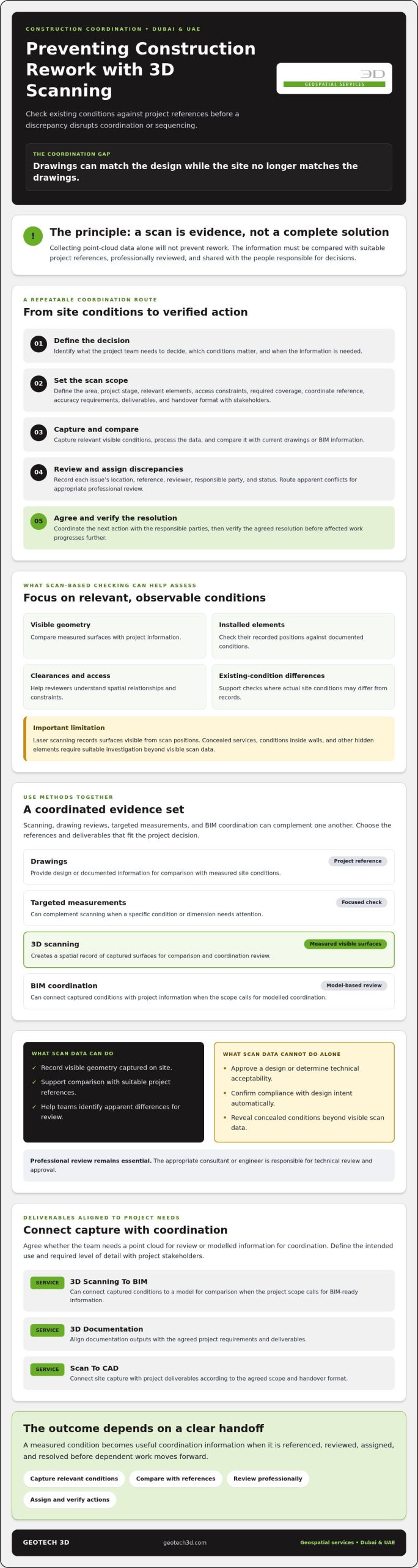
A practical workflow for using scan findings to prevent rework
A scan finding needs a clear route from observation to decision, action, and verification. Without assigned ownership and a recorded outcome, a discrepancy can remain visible in the data but unresolved in the field. Use the project’s established design, coordination, and quality processes to assess and approve any required change.
A repeatable workflow can keep the handoff clear:
- Plan: Define the area and decision to check, the required scan coverage and accuracy, and who will review the results.
- Capture and review: Record the relevant site conditions, then compare them with the agreed drawing, model, or other reference.
- Log and assign: Create an issue for each apparent discrepancy, identify the appropriate discipline for review, and set a responsible party and status.
- Resolve and verify: Record the decision, communicate any approved change before affected work proceeds, and confirm the outcome using the project’s agreed inspection or rescan method.
- Close out: Link the verification evidence and final status to the issue record and relevant project reference.
For each discrepancy, record its location, reference, reviewer, responsible party, and status. Add a clear description of what the scan shows, without presenting an initial observation as a confirmed design issue.
Turn a scan finding into an assigned coordination issue
Use distinct stages in the issue record. An observed condition describes what appears in the captured data; a suspected conflict identifies a possible mismatch that needs assessment; and a confirmed design issue reflects a conclusion reached through the project’s review process. Route each issue to the relevant consultant, engineer, or other responsible discipline. Record decisions and communicate potential impacts before dependent construction proceeds.
Verify the correction before closing the issue
Close an issue only after the project’s agreed inspection or rescan method confirms the outcome, not simply because a change was made. Keep the evidence connected to the drawing reference, model location, or coordination record so reviewers can trace what was checked and what decision followed.
Checklist: Locate the finding, link its reference, assign the right reviewer and responsible party, record the approved action, verify the result, and document closure.
This disciplined handoff is central to how to avoid construction rework with 3D scanning: scan evidence informs the process, while project professionals assess and approve the response.
For an overview of GEOTECH 3D’s scanning services and deliverables, explore the service information and consider how it fits the project’s review process.
How GEOTECH 3D can support a scan-led rework-prevention plan
For scanning to support construction coordination, the scope and deliverables need to match the decisions the project team must make. A clear brief establishes which conditions to capture, which references to use, and how the resulting information will be reviewed. This gives contractors, consultants, engineers, and project managers a practical basis for deciding how scan findings fit into their coordination process.
GEOTECH 3D provides 3D Scanning To BIM, 3D Documentation, and Scan To CAD. The appropriate deliverable depends on the project’s intended use. Where teams need BIM-ready information for design coordination, 3D Scanning To BIM can connect captured site conditions with that workflow. GEOTECH 3D’s Scan to BIM presentation lists indoor, outdoor, and over-ceiling data capture capabilities.
What to include in a Dubai project scanning brief
Give the scanning team enough context to understand the site and intended use. A brief for a project in Dubai or elsewhere in the UAE can identify:
- The project stage and the decision the scan should inform.
- The areas and elements to capture, along with known access constraints and safe-access considerations.
- Available reference information, such as relevant drawings or models.
- The intended use and requested deliverables, such as 3D Documentation, Scan To CAD, or 3D Scanning To BIM.
- Who will review the information, manage the handover, and act on any findings.
Ask relevant stakeholders to confirm the required coverage, accuracy, coordinate reference, and data format before finalising the scope. Agree how access will be coordinated with site operations and who will receive and review the handover. These project-specific decisions help ensure the capture is planned around a defined need, rather than collecting information without an agreed use.
Discussing scope and deliverables with GEOTECH 3D
If your team is considering 3D Scanning To BIM or Scan To CAD, bring the project brief, reference information, and intended use into the scope discussion. GEOTECH 3D serves construction and project management firms in Dubai and the UAE. Its stated solutions extend from raw point-cloud data to BIM-ready models compatible with client CAD packages. No scanning approach can guarantee that rework will be avoided, but a well-defined scope can help teams use captured information as part of their review and coordination process.
Understanding how to avoid construction rework with 3D scanning means connecting capture to project decisions, clear review responsibilities, and an agreed handover. GEOTECH 3D’s Dubai office is Ilyaa Tower 2 – Office 101, Damascus St., Al Qusais Industrial 3. Tel +971 4 295 1589.
To discuss project requirements and handover expectations, review GEOTECH 3D’s scanning information before defining the scope.
Make Site Verification Part of Your Coordination Plan
Reducing avoidable rework starts with checking the conditions that matter before dependent work proceeds. 3D scanning can document visible site geometry, but its value depends on comparing the data with suitable project references and routing findings through the right review and approval process.
A repeatable workflow helps teams move from scan capture to assigned action and verified closeout. Choose the capture scope according to the decision at hand, record each discrepancy clearly, and involve the responsible project professionals before making changes. That’s the practical foundation of how to avoid construction rework with 3D scanning.
GEOTECH 3D lists 3D Scanning To BIM, 3D Documentation, and Scan To CAD. Its Scan to BIM presentation identifies indoor, outdoor, and over-ceiling data capture. Discussing project requirements and handover expectations at the outset can help determine which deliverables suit your coordination needs.
With a clear brief and a disciplined review process, your team can make informed decisions from site data and coordinate next steps with confidence. For project leaders seeking specialized consulting to elevate delivery standards and reduce costly site risks, check out PK Services for guidance on driving construction excellence.
Frequently Asked Questions
How does 3D scanning help prevent construction rework?
To understand how to avoid construction rework with 3D scanning, use captured site conditions to check visible geometry against current drawings or BIM before dependent work proceeds. A point cloud can help teams identify apparent differences around openings, installed elements, or clearances. Reviewers must assess each finding, assign an action, and verify the outcome. Scanning itself does not approve changes or prevent every error.
At what stage should a construction project use 3D scanning?
Use 3D scanning when verifying existing or installed conditions can inform an upcoming project decision. This may be during renovation planning, before work depends on a particular interface, or later when the team needs to document visible conditions. Define the area and purpose first. The project team should agree on scan timing, access, coverage, and deliverables so the information is available for the relevant review.
Can a point cloud be compared directly with BIM?
A point cloud can be compared with BIM when the data and model are suitable for the intended review and use a consistent coordinate reference. The comparison may help reviewers assess relationships between captured surfaces and modelled elements. It does not automatically confirm that the model is current or that a detected difference is a defect. A qualified project reviewer should assess apparent deviations and determine the appropriate response.
Does 3D scanning replace site inspections or measurements?
No. 3D scanning, site inspections, and targeted measurements serve different purposes and can complement one another. A scan records visible surfaces within its agreed scope, while an inspection can assess conditions or workmanship that require direct observation. A targeted measurement may answer a specific dimensional question. Select the method according to the decision, required accuracy, and project process, and retain engineering review where technical judgment is needed.
What information should a contractor provide before requesting a 3D scan?
Provide the project stage, areas and elements to capture, access constraints, available drawings or models, intended use, and requested deliverables. Identify who will review the scan and receive the handover. Before agreeing the scope, ask stakeholders to confirm coverage, accuracy, coordinate reference, and data-format requirements. Include site-access and safety considerations so capture planning accounts for operational conditions and responsibilities.
Can 3D scanning detect hidden pipes or services?
Laser scanning captures visible surfaces; it cannot reveal pipes or services concealed inside walls, floors, or ceilings. A visible pipe may appear in the scan, but the point cloud does not establish the location of hidden assets. If subsurface or concealed utility information is required, the project team should identify an appropriate investigation method and define its scope separately.
How do project teams act on discrepancies found in a scan?
Record each finding with its location, relevant drawing or model reference, reviewer, responsible party, and status. Distinguish an observed condition from a suspected conflict, then route it to the appropriate project discipline for assessment. The responsible professionals should document and approve any change through established design and quality processes. Before closing the issue, verify the resolution using the inspection or rescan method agreed for the project.
Search Now
Error: Contact form not found.