

Our Services
Industrial Plant 3D Scanning: From Reality Capture to Reliable Project Data
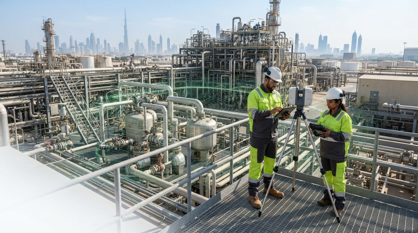
Industrial plant 3D scanning creates value when the capture scope and deliverables are shaped around real project decisions, not simply the volume of data collected. A scan can produce a large point cloud, yet leave engineers without the information they need if the right areas and interfaces were not captured or the output does not fit their workflow.
Existing drawings may not reflect current site conditions, and gaps in spatial information can complicate engineering coordination. A well-planned scan documents the facility as it stands and gives teams a clearer reference for design, retrofit and coordination work. The key is to define the areas and assets to capture, coordinate site access and safety, and agree on the outputs the project team needs.
This article explains what industrial plant scanning captures, how teams use point clouds and BIM-ready or CAD-compatible outputs, and what to define before work begins. It also outlines how to assess project fit and plan scanning in Dubai and elsewhere in the UAE. GEOTECH 3D supports industrial and brownfield facilities with 3D Documentation, Scan To CAD and 3D Scanning To BIM, connecting reality capture with practical project data.
Key Takeaways
- Industrial plant 3D scanning can help teams assess complex existing conditions when records are incomplete or facility layouts have changed.
- A point cloud provides a spatial record for review and further modeling when its coverage and deliverables suit the project’s intended use.
- Compare scanning with conventional measurement based on site complexity, required coverage and the decisions the documentation needs to support.
- Define facility areas, stakeholders, access arrangements, safety requirements and required outputs before planning site capture in Dubai or elsewhere in the UAE.
- GEOTECH 3D connects industrial facility capture with 3D Documentation, Scan To CAD and 3D Scanning To BIM outputs.
Why Industrial Plant 3D Scanning Matters for Existing Facilities
Existing facilities rarely remain exactly as shown in their original drawings. Equipment changes, new pipework, repairs and phased modifications can leave teams with records that are incomplete or out of step with site conditions. Industrial plant 3D scanning uses laser-based capture to document a facility’s existing geometry, giving project teams a clearer spatial reference before they plan changes.
The practical benefit is context. Engineers, designers and asset teams can review how structures, pipelines and other visible elements relate in space. This information can support coordination, engineering development, maintenance planning and project scoping. It can also help teams identify where further investigation is needed before decisions are made. For an overview of the underlying methods and applications, see 3D scanning technology.
What Does 3D Scanning Capture in an Industrial Plant?
Laser scanning records points on surrounding surfaces and combines them into point-cloud data, a three-dimensional spatial record of the captured conditions. Depending on the agreed scope, this may document plant structures, pipelines and facility layouts, showing their positions and relationships. The record represents observed conditions within the capture area. It is not, by itself, a design model, an engineering approval or proof that every element has been captured. Coverage and detail depend on the project scope.
This distinction matters when teams decide what to do with the data. A point cloud can support assessment and later modeling, but it does not make design decisions. Engineers interpret the information against project requirements, and the appropriate output depends on how the data will be used. Define that purpose early so capture focuses on relevant spaces and interfaces, rather than treating a large dataset as an end in itself.
Where Can Industrial Plant Scanning Support Projects?
Industrial plant scanning can support existing-condition documentation in oil and gas facilities, brownfields, power plants and chemical industry settings. These environments may contain layers of installed infrastructure and records created at different stages of a facility’s life. A current spatial reference can help teams understand the context for renovation or modification planning and coordinate work around existing structures and pipelines.
For example, a team planning a change in a brownfield area may need to review how the documented layout relates to the proposed work. A power plant project may need a record of existing spaces and visible plant elements for design coordination. In each case, scanning provides information for review, not a guarantee that conflicts will be found or resolved. The data’s usefulness depends on agreed coverage, suitable processing and deliverables matched to the decisions ahead. Begin with a clear project purpose and defined scope.
How Industrial Plant 3D Scanning Becomes Usable Project Data
A successful capture is more than a collection of scans. Industrial plant 3D scanning becomes useful when the project team defines the information it needs, coordinates site access and agrees how processed data will support design or engineering work. A clear workflow connects field activity to a deliverable the team can review and use.
From Site Scope to Point-Cloud Capture
Start by identifying the areas and interfaces relevant to the project. A modification around existing pipework, for example, may require documentation of the surrounding structure and connections, not just the location where new work is proposed. Define the decisions the information must support, then use that purpose to guide the capture scope and coverage.
Site coordination is part of the technical plan. Access routes, operational constraints, work areas and applicable safety requirements shape how capture can be carried out. Once the scope and access are coordinated, scanning records the selected conditions as point-cloud data. The scans are assembled into a spatial record and reviewed against the agreed coverage. This review helps the team assess whether the dataset is ready for processing or whether a scoped area needs further attention.
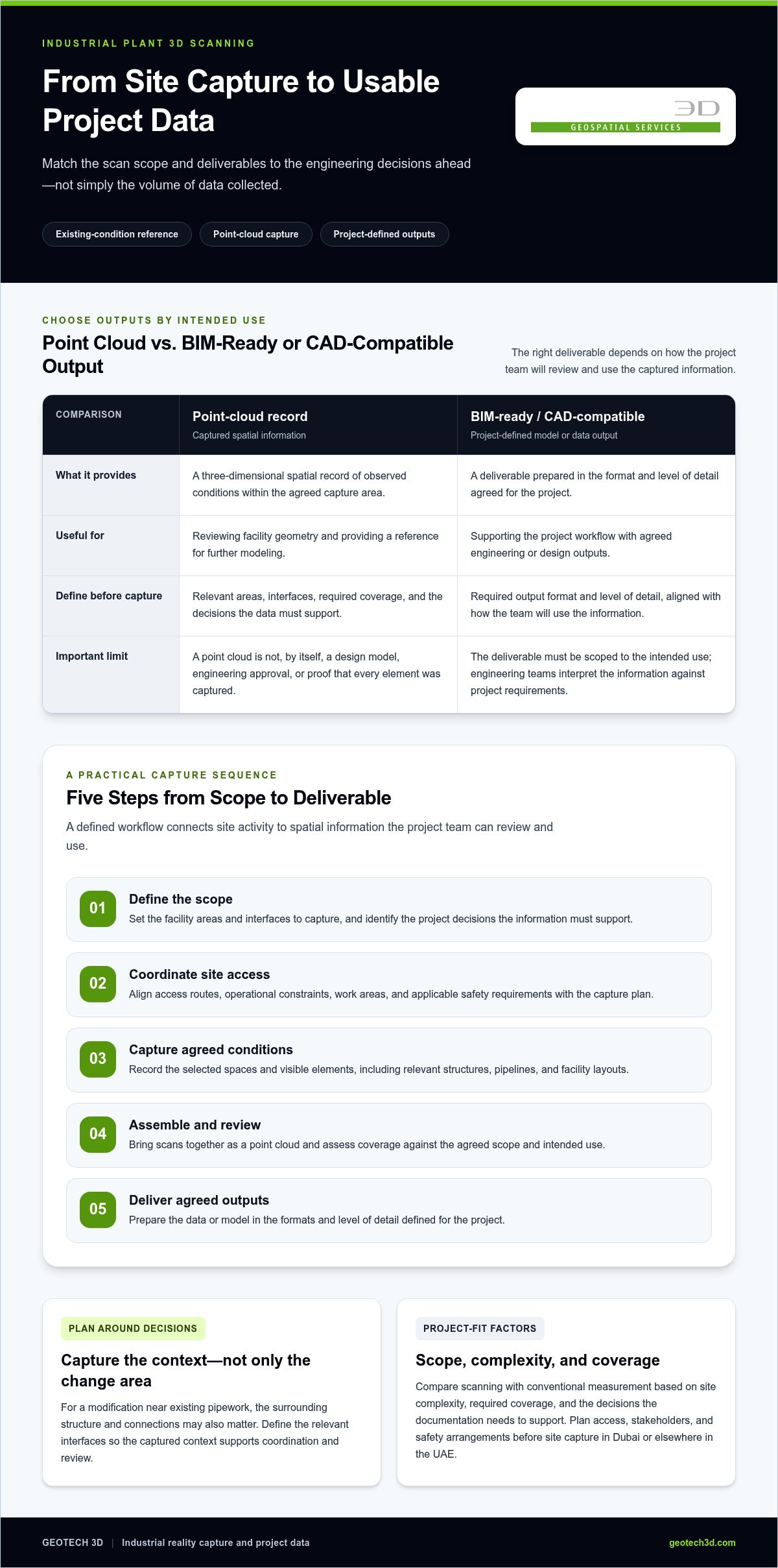
- Define scope: Set the facility areas, interfaces and project decisions the data must support.
- Coordinate access: Align site access, operational requirements and safety arrangements with the capture plan.
- Capture conditions: Record the agreed spaces and visible elements on site.
- Assemble and review: Bring the scans together as a point cloud and assess coverage against the intended use.
- Deliver agreed outputs: Prepare the data or model in the formats and level of detail defined for the project.
The point cloud serves as a spatial record for review and further modeling. Its value depends on how well its coverage and organization match the project’s use. A broad overview may support spatial review, while modeling may require selected elements to be represented at a defined level of detail. The benefits of 3D laser scanning in industrial plants are most relevant when capture and outputs are planned around actual project needs.
From Point Cloud to BIM-Ready or CAD-Compatible Outputs
3D Scanning To BIM turns captured conditions into a BIM model for project teams to use in their workflows. Scan To CAD provides CAD-compatible project information based on the captured site. These are distinct outputs, so choose between them based on intended use, required detail and the client’s working environment. GEOTECH 3D provides end-to-end delivery from raw point-cloud data to BIM-ready models compatible with client CAD packages.
Clarifying file formats, modeled elements and level of detail during scoping helps align processing with downstream use. For teams planning BIM-ready information from scan data, GEOTECH 3D’s scanning and modeling services connect facility capture with project outputs.
When Industrial Plant 3D Scanning Fits Better Than Conventional Documentation
The right documentation method depends on what the project needs to understand. Conventional measurement can suit a task focused on a limited number of dimensions or a clearly defined area. Industrial plant 3D scanning may be more appropriate when teams need broader spatial context, particularly where structures, pipework and other visible elements intersect. Base the decision on required coverage and intended use, not on an assumption that one method suits every task.
Which Plant Project Conditions Make Scanning Useful?
Consider scanning when a brownfield layout is complex, existing records are incomplete, or modifications must be planned around interconnected structural and MEP elements. In oil and gas facilities, power plants and chemical industry settings, spatial relationships can matter as much as individual measurements. A broader captured record can give project teams a shared basis for reviewing the area and developing documentation for the work ahead.
Use the project’s questions to guide the choice. Does the team need a few dimensions, or does it need to review how multiple elements relate across an area? Is the work confined to a simple, accessible location, or does it involve a layered existing layout? The answers help determine whether targeted conventional measurements, scanning or a combination is the better fit.
Project condition: A small, clearly defined area with a limited number of required dimensions.
Documentation need: Targeted measurements for a specific check or design input.
Consideration: Conventional measurement may suit a narrow information need when spatial relationships beyond the immediate area are not central.
Project condition: A complex brownfield area, modification zone or facility with incomplete existing-condition records.
Documentation need: Broader spatial context for reviewing relationships among structures and MEP elements.
Consideration: Scanning can provide wider captured coverage, with scope and outputs defined around the project’s decisions.
Project condition: A defined task that requires both specific dimensions and wider context.
Documentation need: Targeted measurements alongside spatial documentation.
Consideration: A combined approach may suit the scope. Select each method for the information it needs to provide.
What Scanning Does Not Replace
A point cloud is captured survey data, not automatically a coordinated design or approved model. Survey documentation records observed conditions within its agreed scope. Engineering teams interpret that information, assess design requirements and make decisions about proposed work. Modeling and coordination are separate steps, so scanning alone cannot promise a clash-free design, guaranteed savings or uninterrupted operations.
For project teams in Dubai and across the UAE, the practical test is whether the chosen method supplies the information needed for the next decision. GEOTECH 3D’s industrial facility scanning supports this assessment through 3D Documentation, Scan To CAD or 3D Scanning To BIM, depending on the agreed project output. Define the scope first, then match capture and deliverables to the work.
How to Plan an Industrial Plant 3D Scanning Project in Dubai and the UAE
Good preparation gives capture a clear purpose. Before mobilization, align the facility areas to be documented with the decisions the project team needs to make. For industrial plant 3D scanning in Dubai or elsewhere in the UAE, coordinate the scope, site arrangements and final deliverables rather than treating field capture as a standalone activity.
Set the Scope, Access Plan, and Project Interfaces
Map the relevant areas and identify interfaces that matter to engineering or modification work, such as where structures and installed services meet. Include the project manager, engineering leads, facility representatives and other stakeholders responsible for access or operational coordination. Their input helps define boundaries, site constraints and the information capture needs to provide.
Plan access around the facility’s operating conditions and agreed site safety requirements. Identify areas with restricted or changing access, and communicate the capture plan to relevant stakeholders. Safety planning should reflect the site and work scope. Do not base it on assumptions about facility procedures.
Define Deliverables Before Capture Begins
Agree on the intended output and who will use it. 3D Documentation records existing conditions, while Scan To CAD and 3D Scanning To BIM support CAD-compatible or BIM-ready workflows. The appropriate option depends on project decisions, required detail and downstream users, not simply on the amount of data collected.
Use a project brief to make the scope actionable. Record:
- Purpose: The renovation, modification, coordination or documentation task the capture will support.
- Coverage: Facility areas, interfaces and visible elements to include, along with any agreed exclusions.
- Stakeholders: The people coordinating engineering needs, site access, operations and output review.
- Deliverables: Required output type, level of detail, file format and intended recipients.
- Assumptions: Site access conditions, operational constraints and scope boundaries relevant to planning.
Renovation projects particularly benefit from connecting capture scope to the spaces and interfaces affected by the proposed work. Establish which existing conditions are relevant to the design team and how the resulting documentation will be used. This keeps the brief focused without implying that scanning alone resolves engineering or design questions.
GEOTECH 3D coordinates industrial facility scanning with agreed project outputs, from raw point-cloud data to BIM-ready models compatible with client CAD packages. Clear scope and site coordination connect field capture to the information the project team needs. Read more about GEOTECH 3D’s industrial scanning services.
GEOTECH 3D Industrial Plant Scanning: From Capture to Engineering-Ready Data
For industrial facilities, a scan’s value depends on how well the captured conditions connect to the project’s next steps. GEOTECH 3D provides 3D laser scanning for industrial facilities and brownfields, including oil and gas settings, with services that connect site capture to defined documentation, CAD and BIM outputs. Scope and site coordination shape that process from the outset.
A Connected Service Path for Industrial Facilities
3D Documentation provides a digital record of existing facility conditions within the agreed scope. Project teams can review this information as they plan engineering or modification work. From captured point-cloud data, the next step may be Scan To CAD for CAD-compatible project information or 3D Scanning To BIM for BIM-ready modeling. Each output serves a different workflow, so the choice depends on what the project team needs to do with the information.
GEOTECH 3D provides end-to-end delivery from raw point-cloud data to BIM-ready models compatible with client CAD packages. This connects capture and processing with the intended project environment, rather than leaving teams with data that has no defined use. Before work begins, stakeholders can establish the areas to document, relevant interfaces, required detail and output format. These decisions align the scope with engineering needs and set clear expectations for the deliverables.
Industrial sites require careful coordination. GEOTECH 3D works to meet strict safety requirements and tight schedules, with planning shaped around the facility and project scope. Clear communication about site constraints and access supports an organized capture process. Specific arrangements depend on the facility’s operating conditions and requirements.
Discuss Your Industrial Plant Scanning Requirements
To define project fit, prepare a concise brief covering the facility type, areas of interest, purpose of the documentation, site constraints and required outputs. Note whether the team needs 3D Documentation, Scan To CAD or 3D Scanning To BIM, and identify the people who will use or review the information. This gives the scope discussion a practical starting point without assuming every plant needs the same coverage or model detail.
For projects in Dubai and across the UAE, aligning facility access, operational coordination and deliverable requirements early connects capture planning to the decisions the project must support. GEOTECH 3D’s industrial plant 3D scanning services turn existing conditions into usable project data, with outputs planned around the agreed scope.
Set Your Plant Project Up for Its Next Decision
The value of industrial plant 3D scanning is clearest when captured information is planned around the decisions ahead. Before work begins, align the areas of interest, site constraints and intended use of the deliverables. This gives engineering and project teams a purposeful starting point for coordinating existing conditions with proposed work.
GEOTECH 3D specializes in accurate 3D models for oil and gas facilities and brownfields. Its end-to-end service can progress from point-cloud data to BIM-ready models compatible with client CAD packages. With the project scope defined, teams can connect site capture to a practical output without treating data collection as the final objective.
Bring together the facility type, relevant areas, access considerations and preferred deliverables to frame the project discussion. A clear brief helps establish how scanning can fit the work and what information the team needs to move forward.
With the right scope and a clear path from capture to project data, your team can approach its next decision with a more useful record of existing conditions.
Frequently Asked Questions
What is industrial plant 3D scanning?
Industrial plant 3D scanning uses laser-based capture to record visible existing conditions across a facility. The measurements form point-cloud data, a digital representation of scanned surfaces and their spatial relationships. Teams can use this record to examine structures, pipelines and other areas within the agreed scope. It documents what was captured; it is not automatically a design model, engineering assessment or approval.
How does 3D laser scanning help document an industrial plant?
3D laser scanning gives project teams a spatial reference for reviewing existing facility conditions. For example, engineers coordinating work near a pipe rack can use the captured information to understand the documented relationship between the structure and surrounding elements. The record can inform coordination and follow-on modeling, but it does not resolve design questions by itself. Its usefulness depends on appropriate coverage, review and outputs aligned with the work.
Can an industrial plant be scanned while operations are active?
Scanning may be planned at an operating facility, but whether and how it can proceed depends on site conditions, access arrangements and operational coordination. Identify active work areas, access limitations and relevant site procedures before planning capture. Facility stakeholders can help establish where and when access is appropriate. The capture plan should reflect those conditions rather than assume operations can continue unchanged.
What deliverables can come from industrial plant 3D scanning?
Deliverables can include point-cloud data, 3D Documentation, Scan To CAD or 3D Scanning To BIM. Point clouds preserve captured spatial information for review and further modeling. 3D Documentation provides a digital record of existing conditions; Scan To CAD supports CAD-compatible information, while 3D Scanning To BIM develops BIM-ready models. The project purpose, required detail and downstream users should guide the agreed output.
When should a plant project use 3D scanning instead of conventional measurements?
Choose based on complexity, required coverage and the decisions the documentation must support. Conventional measurements may suit a limited task focused on specific dimensions in a defined area. Scanning can be useful when a project needs broader spatial context, such as reviewing several visible structural and MEP elements together. Some scopes may benefit from combining approaches. Neither method is universally best; the project brief should determine the fit.
How is a point cloud used for plant engineering?
A point cloud can be reviewed as a spatial reference and may serve as the basis for further CAD or BIM modeling. An engineering team could use it to examine existing geometry around a proposed modification, then develop the design using its own criteria and process. The point cloud represents captured conditions within scope; engineers remain responsible for interpretation, design decisions and any required approval.
What should a project team prepare before industrial plant scanning in Dubai?
Before industrial plant scanning in Dubai, prepare a brief that identifies facility areas, project purpose, relevant stakeholders and required outputs. Note access arrangements, operational constraints and site-specific safety planning needs, then align these with the capture scope. State whether the team needs 3D Documentation, Scan To CAD or 3D Scanning To BIM, and identify who will use the deliverables. This gives planning a clear project basis.
To plan industrial plant 3D scanning in Dubai or elsewhere in the UAE, contact GEOTECH 3D with your facility areas, access considerations and intended deliverables.
Industrial plant 3D scanning creates value when the capture scope and deliverables are shaped around real project decisions, not simply the volume of data collected. A scan can produce a large point cloud, yet leave engineers without the information they need if the right areas and interfaces were not captured or the output does not fit their workflow.
Existing drawings may not reflect current site conditions, and gaps in spatial information can complicate engineering coordination. A well-planned scan documents the facility as it stands and gives teams a clearer reference for design, retrofit and coordination work. The key is to define the areas and assets to capture, coordinate site access and safety, and agree on the outputs the project team needs.
This article explains what industrial plant scanning captures, how teams use point clouds and BIM-ready or CAD-compatible outputs, and what to define before work begins. It also outlines how to assess project fit and plan scanning in Dubai and elsewhere in the UAE. GEOTECH 3D supports industrial and brownfield facilities with 3D Documentation, Scan To CAD and 3D Scanning To BIM, connecting reality capture with practical project data.
Key Takeaways
- Industrial plant 3D scanning can help teams assess complex existing conditions when records are incomplete or facility layouts have changed.
- A point cloud provides a spatial record for review and further modeling when its coverage and deliverables suit the project’s intended use.
- Compare scanning with conventional measurement based on site complexity, required coverage and the decisions the documentation needs to support.
- Define facility areas, stakeholders, access arrangements, safety requirements and required outputs before planning site capture in Dubai or elsewhere in the UAE.
- GEOTECH 3D connects industrial facility capture with 3D Documentation, Scan To CAD and 3D Scanning To BIM outputs.
Why Industrial Plant 3D Scanning Matters for Existing Facilities
Existing facilities rarely remain exactly as shown in their original drawings. Equipment changes, new pipework, repairs and phased modifications can leave teams with records that are incomplete or out of step with site conditions. Industrial plant 3D scanning uses laser-based capture to document a facility’s existing geometry, giving project teams a clearer spatial reference before they plan changes.
The practical benefit is context. Engineers, designers and asset teams can review how structures, pipelines and other visible elements relate in space. This information can support coordination, engineering development, maintenance planning and project scoping. It can also help teams identify where further investigation is needed before decisions are made. For an overview of the underlying methods and applications, see 3D scanning technology.
What Does 3D Scanning Capture in an Industrial Plant?
Laser scanning records points on surrounding surfaces and combines them into point-cloud data, a three-dimensional spatial record of the captured conditions. Depending on the agreed scope, this may document plant structures, pipelines and facility layouts, showing their positions and relationships. The record represents observed conditions within the capture area. It is not, by itself, a design model, an engineering approval or proof that every element has been captured. Coverage and detail depend on the project scope.
This distinction matters when teams decide what to do with the data. A point cloud can support assessment and later modeling, but it does not make design decisions. Engineers interpret the information against project requirements, and the appropriate output depends on how the data will be used. Define that purpose early so capture focuses on relevant spaces and interfaces, rather than treating a large dataset as an end in itself.
Where Can Industrial Plant Scanning Support Projects?
Industrial plant scanning can support existing-condition documentation in oil and gas facilities, brownfields, power plants and chemical industry settings. These environments may contain layers of installed infrastructure and records created at different stages of a facility’s life. A current spatial reference can help teams understand the context for renovation or modification planning and coordinate work around existing structures and pipelines.
For example, a team planning a change in a brownfield area may need to review how the documented layout relates to the proposed work. A power plant project may need a record of existing spaces and visible plant elements for design coordination. In each case, scanning provides information for review, not a guarantee that conflicts will be found or resolved. The data’s usefulness depends on agreed coverage, suitable processing and deliverables matched to the decisions ahead. Begin with a clear project purpose and defined scope.
How Industrial Plant 3D Scanning Becomes Usable Project Data
A successful capture is more than a collection of scans. Industrial plant 3D scanning becomes useful when the project team defines the information it needs, coordinates site access and agrees how processed data will support design or engineering work. A clear workflow connects field activity to a deliverable the team can review and use.
From Site Scope to Point-Cloud Capture
Start by identifying the areas and interfaces relevant to the project. A modification around existing pipework, for example, may require documentation of the surrounding structure and connections, not just the location where new work is proposed. Define the decisions the information must support, then use that purpose to guide the capture scope and coverage.
Site coordination is part of the technical plan. Access routes, operational constraints, work areas and applicable safety requirements shape how capture can be carried out. Once the scope and access are coordinated, scanning records the selected conditions as point-cloud data. The scans are assembled into a spatial record and reviewed against the agreed coverage. This review helps the team assess whether the dataset is ready for processing or whether a scoped area needs further attention.
- Define scope: Set the facility areas, interfaces and project decisions the data must support.
- Coordinate access: Align site access, operational requirements and safety arrangements with the capture plan.
- Capture conditions: Record the agreed spaces and visible elements on site.
- Assemble and review: Bring the scans together as a point cloud and assess coverage against the intended use.
- Deliver agreed outputs: Prepare the data or model in the formats and level of detail defined for the project.
The point cloud serves as a spatial record for review and further modeling. Its value depends on how well its coverage and organization match the project’s use. A broad overview may support spatial review, while modeling may require selected elements to be represented at a defined level of detail. The benefits of 3D laser scanning in industrial plants are most relevant when capture and outputs are planned around actual project needs.
From Point Cloud to BIM-Ready or CAD-Compatible Outputs
3D Scanning To BIM turns captured conditions into a BIM model for project teams to use in their workflows. Scan To CAD provides CAD-compatible project information based on the captured site. These are distinct outputs, so choose between them based on intended use, required detail and the client’s working environment. GEOTECH 3D provides end-to-end delivery from raw point-cloud data to BIM-ready models compatible with client CAD packages.
Clarifying file formats, modeled elements and level of detail during scoping helps align processing with downstream use. For teams planning BIM-ready information from scan data, GEOTECH 3D’s scanning and modeling services connect facility capture with project outputs.
When Industrial Plant 3D Scanning Fits Better Than Conventional Documentation
The right documentation method depends on what the project needs to understand. Conventional measurement can suit a task focused on a limited number of dimensions or a clearly defined area. Industrial plant 3D scanning may be more appropriate when teams need broader spatial context, particularly where structures, pipework and other visible elements intersect. Base the decision on required coverage and intended use, not on an assumption that one method suits every task.
Which Plant Project Conditions Make Scanning Useful?
Consider scanning when a brownfield layout is complex, existing records are incomplete, or modifications must be planned around interconnected structural and MEP elements. In oil and gas facilities, power plants and chemical industry settings, spatial relationships can matter as much as individual measurements. A broader captured record can give project teams a shared basis for reviewing the area and developing documentation for the work ahead.
Use the project’s questions to guide the choice. Does the team need a few dimensions, or does it need to review how multiple elements relate across an area? Is the work confined to a simple, accessible location, or does it involve a layered existing layout? The answers help determine whether targeted conventional measurements, scanning or a combination is the better fit.
Project condition: A small, clearly defined area with a limited number of required dimensions.
Documentation need: Targeted measurements for a specific check or design input.
Consideration: Conventional measurement may suit a narrow information need when spatial relationships beyond the immediate area are not central.
Project condition: A complex brownfield area, modification zone or facility with incomplete existing-condition records.
Documentation need: Broader spatial context for reviewing relationships among structures and MEP elements.
Consideration: Scanning can provide wider captured coverage, with scope and outputs defined around the project’s decisions.
Project condition: A defined task that requires both specific dimensions and wider context.
Documentation need: Targeted measurements alongside spatial documentation.
Consideration: A combined approach may suit the scope. Select each method for the information it needs to provide.
What Scanning Does Not Replace
A point cloud is captured survey data, not automatically a coordinated design or approved model. Survey documentation records observed conditions within its agreed scope. Engineering teams interpret that information, assess design requirements and make decisions about proposed work. Modeling and coordination are separate steps, so scanning alone cannot promise a clash-free design, guaranteed savings or uninterrupted operations.
For project teams in Dubai and across the UAE, the practical test is whether the chosen method supplies the information needed for the next decision. GEOTECH 3D’s industrial facility scanning supports this assessment through 3D Documentation, Scan To CAD or 3D Scanning To BIM, depending on the agreed project output. Define the scope first, then match capture and deliverables to the work.
How to Plan an Industrial Plant 3D Scanning Project in Dubai and the UAE
Good preparation gives capture a clear purpose. Before mobilization, align the facility areas to be documented with the decisions the project team needs to make. For industrial plant 3D scanning in Dubai or elsewhere in the UAE, coordinate the scope, site arrangements and final deliverables rather than treating field capture as a standalone activity.
Set the Scope, Access Plan, and Project Interfaces
Map the relevant areas and identify interfaces that matter to engineering or modification work, such as where structures and installed services meet. Include the project manager, engineering leads, facility representatives and other stakeholders responsible for access or operational coordination. Their input helps define boundaries, site constraints and the information capture needs to provide.
Plan access around the facility’s operating conditions and agreed site safety requirements. Identify areas with restricted or changing access, and communicate the capture plan to relevant stakeholders. Safety planning should reflect the site and work scope. Do not base it on assumptions about facility procedures.
Define Deliverables Before Capture Begins
Agree on the intended output and who will use it. 3D Documentation records existing conditions, while Scan To CAD and 3D Scanning To BIM support CAD-compatible or BIM-ready workflows. The appropriate option depends on project decisions, required detail and downstream users, not simply on the amount of data collected.
Use a project brief to make the scope actionable. Record:
- Purpose: The renovation, modification, coordination or documentation task the capture will support.
- Coverage: Facility areas, interfaces and visible elements to include, along with any agreed exclusions.
- Stakeholders: The people coordinating engineering needs, site access, operations and output review.
- Deliverables: Required output type, level of detail, file format and intended recipients.
- Assumptions: Site access conditions, operational constraints and scope boundaries relevant to planning.
Renovation projects particularly benefit from connecting capture scope to the spaces and interfaces affected by the proposed work. Establish which existing conditions are relevant to the design team and how the resulting documentation will be used. This keeps the brief focused without implying that scanning alone resolves engineering or design questions.
GEOTECH 3D coordinates industrial facility scanning with agreed project outputs, from raw point-cloud data to BIM-ready models compatible with client CAD packages. Clear scope and site coordination connect field capture to the information the project team needs. Read more about GEOTECH 3D’s industrial scanning services.
GEOTECH 3D Industrial Plant Scanning: From Capture to Engineering-Ready Data
For industrial facilities, a scan’s value depends on how well the captured conditions connect to the project’s next steps. GEOTECH 3D provides 3D laser scanning for industrial facilities and brownfields, including oil and gas settings, with services that connect site capture to defined documentation, CAD and BIM outputs. Scope and site coordination shape that process from the outset.
A Connected Service Path for Industrial Facilities
3D Documentation provides a digital record of existing facility conditions within the agreed scope. Project teams can review this information as they plan engineering or modification work. From captured point-cloud data, the next step may be Scan To CAD for CAD-compatible project information or 3D Scanning To BIM for BIM-ready modeling. Each output serves a different workflow, so the choice depends on what the project team needs to do with the information.
GEOTECH 3D provides end-to-end delivery from raw point-cloud data to BIM-ready models compatible with client CAD packages. This connects capture and processing with the intended project environment, rather than leaving teams with data that has no defined use. Before work begins, stakeholders can establish the areas to document, relevant interfaces, required detail and output format. These decisions align the scope with engineering needs and set clear expectations for the deliverables.
Industrial sites require careful coordination. GEOTECH 3D works to meet strict safety requirements and tight schedules, with planning shaped around the facility and project scope. Clear communication about site constraints and access supports an organized capture process. Specific arrangements depend on the facility’s operating conditions and requirements.
Discuss Your Industrial Plant Scanning Requirements
To define project fit, prepare a concise brief covering the facility type, areas of interest, purpose of the documentation, site constraints and required outputs. Note whether the team needs 3D Documentation, Scan To CAD or 3D Scanning To BIM, and identify the people who will use or review the information. This gives the scope discussion a practical starting point without assuming every plant needs the same coverage or model detail.
For projects in Dubai and across the UAE, aligning facility access, operational coordination and deliverable requirements early connects capture planning to the decisions the project must support. GEOTECH 3D’s industrial plant 3D scanning services turn existing conditions into usable project data, with outputs planned around the agreed scope.
Set Your Plant Project Up for Its Next Decision
The value of industrial plant 3D scanning is clearest when captured information is planned around the decisions ahead. Before work begins, align the areas of interest, site constraints and intended use of the deliverables. This gives engineering and project teams a purposeful starting point for coordinating existing conditions with proposed work.
GEOTECH 3D specializes in accurate 3D models for oil and gas facilities and brownfields. Its end-to-end service can progress from point-cloud data to BIM-ready models compatible with client CAD packages. With the project scope defined, teams can connect site capture to a practical output without treating data collection as the final objective.
Bring together the facility type, relevant areas, access considerations and preferred deliverables to frame the project discussion. A clear brief helps establish how scanning can fit the work and what information the team needs to move forward.
With the right scope and a clear path from capture to project data, your team can approach its next decision with a more useful record of existing conditions.
Frequently Asked Questions
What is industrial plant 3D scanning?
Industrial plant 3D scanning uses laser-based capture to record visible existing conditions across a facility. The measurements form point-cloud data, a digital representation of scanned surfaces and their spatial relationships. Teams can use this record to examine structures, pipelines and other areas within the agreed scope. It documents what was captured; it is not automatically a design model, engineering assessment or approval.
How does 3D laser scanning help document an industrial plant?
3D laser scanning gives project teams a spatial reference for reviewing existing facility conditions. For example, engineers coordinating work near a pipe rack can use the captured information to understand the documented relationship between the structure and surrounding elements. The record can inform coordination and follow-on modeling, but it does not resolve design questions by itself. Its usefulness depends on appropriate coverage, review and outputs aligned with the work.
Can an industrial plant be scanned while operations are active?
Scanning may be planned at an operating facility, but whether and how it can proceed depends on site conditions, access arrangements and operational coordination. Identify active work areas, access limitations and relevant site procedures before planning capture. Facility stakeholders can help establish where and when access is appropriate. The capture plan should reflect those conditions rather than assume operations can continue unchanged.
What deliverables can come from industrial plant 3D scanning?
Deliverables can include point-cloud data, 3D Documentation, Scan To CAD or 3D Scanning To BIM. Point clouds preserve captured spatial information for review and further modeling. 3D Documentation provides a digital record of existing conditions; Scan To CAD supports CAD-compatible information, while 3D Scanning To BIM develops BIM-ready models. The project purpose, required detail and downstream users should guide the agreed output.
When should a plant project use 3D scanning instead of conventional measurements?
Choose based on complexity, required coverage and the decisions the documentation must support. Conventional measurements may suit a limited task focused on specific dimensions in a defined area. Scanning can be useful when a project needs broader spatial context, such as reviewing several visible structural and MEP elements together. Some scopes may benefit from combining approaches. Neither method is universally best; the project brief should determine the fit.
How is a point cloud used for plant engineering?
A point cloud can be reviewed as a spatial reference and may serve as the basis for further CAD or BIM modeling. An engineering team could use it to examine existing geometry around a proposed modification, then develop the design using its own criteria and process. The point cloud represents captured conditions within scope; engineers remain responsible for interpretation, design decisions and any required approval.
What should a project team prepare before industrial plant scanning in Dubai?
Before industrial plant scanning in Dubai, prepare a brief that identifies facility areas, project purpose, relevant stakeholders and required outputs. Note access arrangements, operational constraints and site-specific safety planning needs, then align these with the capture scope. State whether the team needs 3D Documentation, Scan To CAD or 3D Scanning To BIM, and identify who will use the deliverables. This gives planning a clear project basis.
To plan industrial plant 3D scanning in Dubai or elsewhere in the UAE, contact GEOTECH 3D with your facility areas, access considerations and intended deliverables.
Search Now
Error: Contact form not found.