

Our Services
Underground Utility Surveys for Construction in Dubai
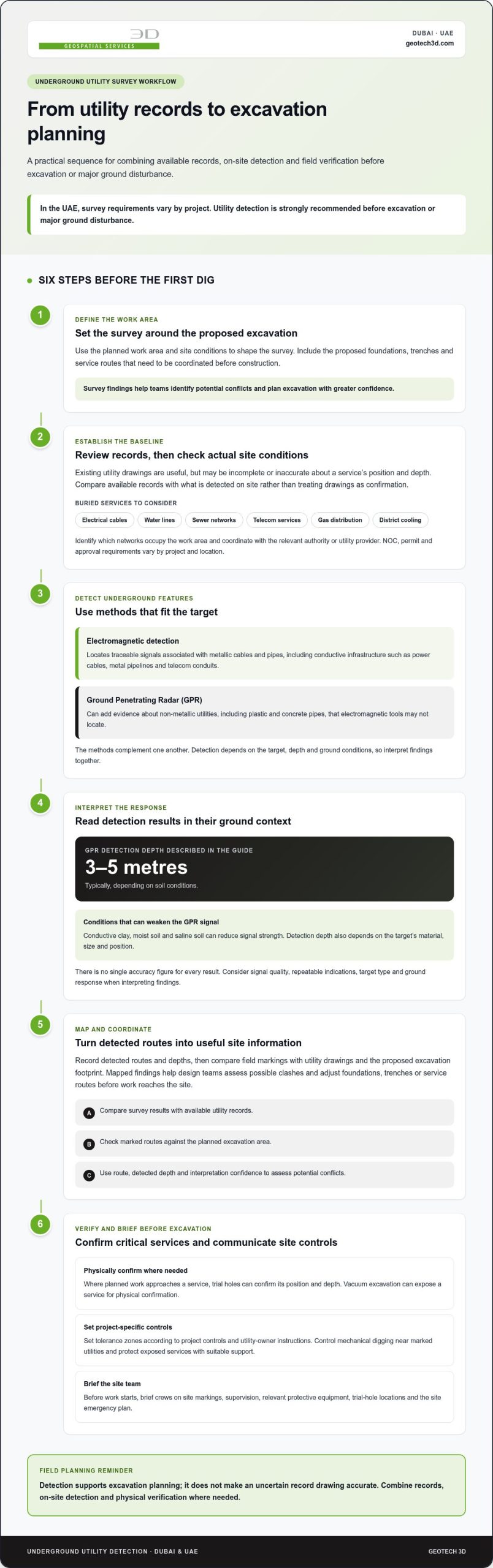
Excavation should start with a clear picture of what lies below. In the UAE, utility survey requirements vary by project, but surveys are strongly recommended before excavation or major ground disturbance. Preventing underground utility strikes in Dubai begins by identifying buried services before construction starts.
Existing utility drawings are useful, but they may not reflect actual site conditions or show every service. Combining available records with on-site detection helps construction teams identify potential conflicts and plan excavation with greater confidence.
This guide explains when to survey, what electromagnetic detection and ground penetrating radar (GPR) can reveal, and how survey findings support design and site planning. It also covers the impact of damaged or missing tracer wires, factors that can affect detection, and how mapped underground infrastructure informs construction across Dubai and the UAE.
Key Takeaways
- Plan utility detection before excavation or heavy ground disturbance, using site conditions and the proposed work area to shape the survey.
- Use electromagnetic detection to trace metallic cables and pipes, and consider complementary methods for services that are difficult to locate.
- Learn how GPR can help identify non-metallic utilities and what ground conditions can affect its readings.
- Turn survey findings into mapped information that supports excavation planning and coordination with design teams.
- See how GEOTECH 3D’s surveying services can support projects that need reliable site data for planning and construction.
Do I Need an Underground Utility Survey Before Construction in the UAE?
Yes. In the UAE, survey requirements vary by project, but utility detection is strongly recommended before excavation or major ground disturbance. Survey data helps contractors coordinate designs, identify conflicts, and plan safer digging.
Survey Data for Excavation and Design
A survey compares available utility drawings with detected site conditions. This is important in Dubai, where records may be incomplete or inaccurate about a service’s position and depth. Use the resulting map to coordinate proposed foundations, trenches, and service routes before construction. Detected routes and depths give design teams useful information to assess clashes and adjust plans before work reaches the site.
Contractors can compare field markings with the excavation footprint and brief crews on detected services. Trial holes can physically confirm a utility’s position and depth where planned work approaches it.
Risk Reduction and Safe Digging
Detection can locate buried electrical cables, water lines, sewer networks, telecom services, gas distribution lines, and district cooling pipelines. A strike can cause electrical shock, gas leaks, flooding, service disruption, and delays. Set a tolerance zone around detected services according to project controls and utility-owner instructions, rather than assuming one clearance applies everywhere.
Trial holes or vacuum excavation can expose a service for physical confirmation. Control mechanical digging near marked utilities, and protect exposed services with suitable support. Before excavation, brief crews on site markings, supervision, and protective equipment relevant to the work.
NOC, Permits, and Approvals
NOC requirements vary by project and the infrastructure affected. Before excavating near utilities, identify which networks occupy the work area and coordinate the proposed work with the relevant authorities or utility providers.
Permits, approvals, and fees also depend on the project and its location. Work affecting public roads, traffic flow, or road reinstatement falls within the Roads and Transport Authority’s remit. Do not assume another site’s approval conditions or fees apply to your project.
Utility damage can create safety risks, service disruption, delays, and financial penalties. Consequences and liability depend on the incident and applicable project requirements. After a strike, stop work, keep people clear, and notify the affected operator and site lead.
Authorities and Utility Provider Coordination
Dubai Municipality oversees general construction, environmental standards, and master planning. DEWA governs electricity and water infrastructure. The Roads and Transport Authority controls work affecting public roads, traffic flow, and reinstatement. Etisalat and du have specific requirements for their telecommunications networks.
Identify which networks cross the excavation area, then coordinate with the relevant authority or operator. Review available records alongside site detection results. Before work starts, brief supervisors and equipment operators on marked routes, trial-hole locations, trench controls, and the site emergency plan.
If a utility is struck, stop work and move people away from immediate danger. Follow the site emergency plan, contact emergency services if there is immediate danger, and notify the affected utility operator using the project’s emergency contacts.
Electromagnetic detection of metallic utilities
Electromagnetic detection locates metallic services, while GPR can add evidence about non-metallic objects. The methods and their accuracy depend on the target, depth, and ground conditions, so survey results should be interpreted together.
Electromagnetic and Radio Detection
Electromagnetic locators trace signals associated with metallic cables and pipes. They are useful for identifying conductive infrastructure, including power cables, metal pipelines, and telecom conduits. The detected route can then be marked on the ground for construction planning.
Radio detection uses a locator to trace a detectable signal along metallic infrastructure. The survey team records the route and considers interruptions or weak responses before interpreting the result. A metallic pipe that carries no usable signal may require another detection method.
For engineering decisions, contractors should compare field markings with available utility drawings and the proposed excavation footprint. The route, detected depth, and confidence in the interpretation help design teams assess possible conflicts. Detection alone does not make an uncertain record drawing accurate.
Detection Method Accuracy
Electromagnetic location is suited to metallic targets that provide a traceable response. GPR sends high-frequency signals into the ground and processes reflections from buried objects or changes in soil. It can reveal non-metallic utilities, including plastic and concrete pipes, that electromagnetic tools may not locate.
GPR can typically detect utilities up to 3-5 metres deep, depending on soil conditions. Conductive clay, moist soil, and saline soil can weaken its signal. In Dubai, detection depth therefore depends on the local ground and the target’s material, size, and position.
No single accuracy figure applies to every detection result. Surveyors interpret signal quality, repeatable indications, target type, and ground response. Combining electromagnetic location with systematic GPR scanning can help distinguish a likely utility route from other buried features. Markings and recorded coordinates make the findings useful for design and site planning.
Where a utility is critical to the excavation design, use detection results to guide further verification. Physical confirmation may be appropriate before work proceeds close to the indicated route. This is especially relevant when records and field signals differ, or when the target’s identity remains uncertain.
For projects requiring mapped detection results, utilities mapping and GPR can support the assessment of metallic and non-metallic underground services.
Mapping utilities with missing or damaged tracer wires
A missing or damaged tracer wire can prevent direct signal tracing along a utility. Underground surveys combine detection results and site observations to map routes for construction planning.
Utility Location, Depth, and Type Mapping
A utility map can record detected routes, depths, connection points, and infrastructure types. When tracer wires provide no usable signal, GPR can help identify buried objects by detecting changes in their response to radar signals. Electromagnetic detection can still locate metallic utilities when a traceable signal is available.
Surveyors can record detected positions as three-dimensional GPS or GNSS coordinates. Contractors can compare the mapped route and depth with proposed excavation areas and utility drawings.
Mapping Purpose and Construction Conflicts
Utility mapping turns field detection into information that design and construction teams can use. Overlaying mapped routes with proposed foundations, service corridors, or trench alignments helps identify potential conflicts before excavation. For example, a proposed trench crossing a mapped water line can be reviewed during design coordination.
Conflict analysis also helps teams plan where further investigation may be needed. If a mapped route differs from an existing drawing, treat it as a design coordination issue rather than dismissing it as a drafting discrepancy.
A practical workflow starts with gathering available utility drawings and marking the planned work area. Surveyors then scan accessible ground, record detected indications, and relate those observations to site features. This comparison is important when older drawings show approximate routes or omit later changes.
When tracer wires are missing, the map should distinguish detected evidence from information taken only from records. This helps engineers understand which routes were located in the field and which remain based on drawings. It also gives contractors a clearer basis for sequencing excavation and protecting known services.
Survey deliverables can show utility locations, depths, and types in mapped plans or reports. Depending on project needs, information can be processed into two-dimensional or three-dimensional maps in GIS or CAD formats. Clear labels and consistent coordinates help design teams compare utilities with proposed works.
Mapping supports more than excavation planning. Asset owners can use documented routes and connection points for maintenance planning, while design teams coordinate new infrastructure around existing services. In Dubai, recording detected conditions also helps teams identify where field evidence differs from available utility drawings.
Before construction, review the map against the final excavation footprint and proposed design. Flag crossings, close approaches, and uncertain routes for further verification. This gives contractors and engineers a shared reference to plan work and reduce the risk of utility damage, service disruption, and avoidable redesign.
Underground utility surveys in smart infrastructure planning
Survey planning connects buried services with proposed construction and future infrastructure needs. In Dubai, the survey scope depends on available records, site conditions, and excavation plans.
For a new building, redevelopment, or service corridor, start by defining the planned work area. Review available as-built records from DEWA, Dubai Municipality, and utility authorities before setting the scan grid. This helps survey teams target relevant ground and compare detected features with recorded routes.
Survey Planning and Interpretation
Plan GPR coverage around the excavation extent, existing records, and accessible surface conditions. Systematic scanning produces radar responses that must be interpreted alongside other survey evidence. For example, a linear response crossing a proposed trench can be marked for design review rather than treated as a confirmed service without assessment.
Survey interpretation turns field indications into usable plans. Teams can record detected routes, depths, and types, then highlight possible conflicts for engineers. This gives contractors a coordinated reference before digging and supports updates to project drawings.
Survey categories help define the level of investigation. PAS 128 Quality Level D is a desktop records review, while Quality Level C combines site reconnaissance with records. Quality Level B uses GPR and radio detection for detailed design and most projects. Quality Level A combines detection with trial-hole verification for high-risk excavation near live services.
ASCE 38 also uses quality levels D, C, B, and A for underground utility survey scoping. These frameworks help teams describe the evidence gathered and the verification approach. The required scope should reflect the design stage, the excavation risk, and how closely proposed works approach buried services.
Site Investigation and Existing Records
Contractors can obtain available utility maps and as-built drawings through relevant utility authorities and network owners. In Dubai, the survey workflow reviews those records before defining field coverage. Compare each drawing with site observations, noting where mapped routes and detected conditions differ.
A topographical survey adds surface information, such as visible features and site levels, to help coordinate the underground plan with proposed works. During redevelopment, this context helps engineers assess how new foundations, access routes, or service connections relate to existing infrastructure.
Treat records as project inputs, not as a substitute for site investigation. A drawing can guide scanning, while detection adds evidence about actual site conditions. Mark discrepancies for review and coordinate design changes before excavation begins.
Survey data can also support smart infrastructure planning beyond immediate construction. GIS or CAD maps can organize utility locations for design coordination, maintenance planning, and future upgrades. Consistent mapping gives project teams a clearer view of buried services across connected work areas.
Ground Penetrating Radar (GPR)
Ground penetrating radar helps locate buried utilities by interpreting signals reflected from underground objects. In Dubai, survey teams use its results alongside site observations to build a practical picture of the ground before construction. GPR is therefore a useful tool for planning safer excavation.
How Ground Penetrating Radar Works
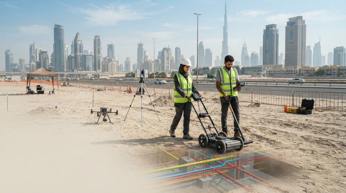
A GPR unit sends high-frequency signals into the ground as it moves across a planned survey area. Buried objects and changes in soil reflect those signals, which the equipment records as radar data. Surveyors interpret patterns in the data to identify possible pipes, conduits, and buried structures.
GPR can help detect non-metallic services, including plastic water and drainage lines, when sufficient contrast exists with surrounding soil. Detection depth depends on ground conditions and the target. GPR can typically detect utilities up to 3-5 metres deep, while conductive clay, moist soil, or saline soil can weaken the signal.
Survey planning shapes how useful the results will be. The scan area should reflect the proposed excavation, accessible ground, and available utility records. For example, a planned foundation footprint can guide systematic passes across the ground, helping the survey team interpret possible linear features in context.
Radar responses provide evidence for interpretation, not automatic identification of a pipe’s material or purpose. A possible telecom route, for example, should be assessed alongside other site information and detection results. Where the design depends on a specific utility location, further verification can inform excavation planning.
Ground Marking and Locate Data
After interpreting the scan, the survey team can mark detected utility indications on the ground. Surface markings give construction crews a visible reference before excavation, while recorded GPS coordinates preserve location information for project drawings and coordination.
A useful locate record connects each marked indication with its mapped position and interpreted depth. Teams can compare this information with proposed trenches, foundations, or service corridors. This makes survey findings easier to apply during site planning than radar images without location context.
Systematic coverage matters too. Scan passes should cover the full work area, including the edges of planned excavation where equipment access allows. Recording survey limits helps engineers understand which ground was scanned and where the results apply.
GPR supports utility surveys by adding evidence about buried features that electromagnetic methods may not locate. Its results are most useful when interpreted alongside records, field markings, and the construction design. For teams focused on preventing underground utility strikes in Dubai, these combined outputs help contractors plan where to dig and where further verification may be needed.
GEOTECH 3D: topo survey
GEOTECH 3D can support construction planning with topo survey and GIS & Surveying Services. A topo survey gives project teams surface context to coordinate with underground utility information, proposed excavation areas, and design plans.
Consider this support during early design, redevelopment, or site preparation, when surface conditions need to be considered alongside buried services. For projects that also require existing-structure information, 3D Laser Scanning can add a measured view of above-ground conditions for coordination.
These services complement utility detection; they do not replace on-site verification of buried infrastructure. Share your project requirements with GEOTECH 3D to discuss suitable surveying support.
Carry Better Site Information Into Your Next Project
Make underground information part of project coordination from the outset. Preventing underground utility strikes in Dubai requires teams to connect survey findings with design decisions, excavation planning, and the site information contractors use. This coordination helps address potential conflicts before they become site issues.
The next step is to define the area requiring investigation and how the results will support the project. GEOTECH 3D offers topo survey, 3D Laser Scanning, and Drone Services to support wider site data requirements. These services can contribute relevant spatial context alongside underground utility information, helping project teams plan from a clearer understanding of site conditions.
Bring your project scope, planned works, and available site information together before excavation planning advances. A coordinated approach gives engineers and contractors a stronger basis for their next decisions.
Move forward with clear site information and a considered plan for the work ahead.
Frequently Asked Questions
How deep can GPR detect utilities in Dubai soil?
GPR can typically detect utilities up to 3-5 metres deep, depending on ground conditions. On a Dubai site, conductive clay, moist soil, or saline soil can weaken the radar signal. The target’s material and position also shape the response. Survey teams interpret the readings in context, rather than treating the typical depth as a guaranteed detection limit for every utility.
Can GPR detect plastic pipes?
Yes, GPR can detect plastic pipes when there is sufficient contrast with the surrounding soil. This can help locate buried plastic water or drainage lines that electromagnetic equipment may not trace. For example, a survey team can scan a proposed service corridor and assess radar responses alongside site records. A pipe’s visibility depends on the ground response and conditions around the target.
What information does a Utility Survey report provide?
A utility survey report can identify detected utilities by location, depth, and type. Depending on the survey deliverables, it may include layout plans, depth profiles, radar images, conflict plans, and field records. For a design review, teams can compare a proposed foundation or service connection with existing underground assets using the mapped route, then identify where further verification may affect the work plan.
What is Utility Mapping?
Utility mapping records underground services in a spatial plan or model. It can document detected routes, depths, connection points, and infrastructure types, helping teams understand how services relate to a site. For example, a mapped telecom route can be compared with a proposed access road. Depending on project needs, utility information can be organized in GIS or CAD formats.
What is underground utility scanning and why is it needed before excavation?
Underground utility scanning uses detection methods to investigate buried services before ground is disturbed. GPR can identify responses from metallic and non-metallic objects, while electromagnetic locators trace suitable metallic infrastructure. Scanning helps contractors plan around potential service conflicts. On a redevelopment site, this information can guide excavation and indicate where a trial hole or other physical verification may be necessary.
What are Dubai’s minimum clearance distances and safe excavation practices around buried cables and pipelines?
Use clearance requirements and work controls set for the specific service and project, rather than applying one assumed distance to every cable or pipeline. Before excavation, review marked routes and coordinate with the relevant network owner. Control mechanical digging near indicated services, and use trial holes or vacuum excavation to confirm positions where needed. Support exposed services during subsequent work.
What are Dubai’s requirements for obtaining a No Objection Certificate (NOC) before excavation near underground utilities?
NOC requirements vary by project and the infrastructure affected. Identify the networks in the work area and coordinate the proposed excavation with the relevant authorities or utility providers. Before excavation, check the applicable permit requirements and confirm utility locations.
What training, supervision, and protective equipment help prevent underground utility strikes on Dubai construction sites?
Brief crews on site markings, ensure appropriate supervision, and provide protective equipment relevant to the work. Before excavation, explain detected service routes, trial-hole locations, trench controls, and the site emergency plan.
Excavation should start with a clear picture of what lies below. In the UAE, utility survey requirements vary by project, but surveys are strongly recommended before excavation or major ground disturbance. Preventing underground utility strikes in Dubai begins by identifying buried services before construction starts.
Existing utility drawings are useful, but they may not reflect actual site conditions or show every service. Combining available records with on-site detection helps construction teams identify potential conflicts and plan excavation with greater confidence.
This guide explains when to survey, what electromagnetic detection and ground penetrating radar (GPR) can reveal, and how survey findings support design and site planning. It also covers the impact of damaged or missing tracer wires, factors that can affect detection, and how mapped underground infrastructure informs construction across Dubai and the UAE.
Key Takeaways
- Plan utility detection before excavation or heavy ground disturbance, using site conditions and the proposed work area to shape the survey.
- Use electromagnetic detection to trace metallic cables and pipes, and consider complementary methods for services that are difficult to locate.
- Learn how GPR can help identify non-metallic utilities and what ground conditions can affect its readings.
- Turn survey findings into mapped information that supports excavation planning and coordination with design teams.
- See how GEOTECH 3D’s surveying services can support projects that need reliable site data for planning and construction.
Do I Need an Underground Utility Survey Before Construction in the UAE?
Yes. In the UAE, survey requirements vary by project, but utility detection is strongly recommended before excavation or major ground disturbance. Survey data helps contractors coordinate designs, identify conflicts, and plan safer digging.
Survey Data for Excavation and Design
A survey compares available utility drawings with detected site conditions. This is important in Dubai, where records may be incomplete or inaccurate about a service’s position and depth. Use the resulting map to coordinate proposed foundations, trenches, and service routes before construction. Detected routes and depths give design teams useful information to assess clashes and adjust plans before work reaches the site.
Contractors can compare field markings with the excavation footprint and brief crews on detected services. Trial holes can physically confirm a utility’s position and depth where planned work approaches it.
Risk Reduction and Safe Digging
Detection can locate buried electrical cables, water lines, sewer networks, telecom services, gas distribution lines, and district cooling pipelines. A strike can cause electrical shock, gas leaks, flooding, service disruption, and delays. Set a tolerance zone around detected services according to project controls and utility-owner instructions, rather than assuming one clearance applies everywhere.
Trial holes or vacuum excavation can expose a service for physical confirmation. Control mechanical digging near marked utilities, and protect exposed services with suitable support. Before excavation, brief crews on site markings, supervision, and protective equipment relevant to the work.
NOC, Permits, and Approvals
NOC requirements vary by project and the infrastructure affected. Before excavating near utilities, identify which networks occupy the work area and coordinate the proposed work with the relevant authorities or utility providers.
Permits, approvals, and fees also depend on the project and its location. Work affecting public roads, traffic flow, or road reinstatement falls within the Roads and Transport Authority’s remit. Do not assume another site’s approval conditions or fees apply to your project.
Utility damage can create safety risks, service disruption, delays, and financial penalties. Consequences and liability depend on the incident and applicable project requirements. After a strike, stop work, keep people clear, and notify the affected operator and site lead.
Authorities and Utility Provider Coordination
Dubai Municipality oversees general construction, environmental standards, and master planning. DEWA governs electricity and water infrastructure. The Roads and Transport Authority controls work affecting public roads, traffic flow, and reinstatement. Etisalat and du have specific requirements for their telecommunications networks.
Identify which networks cross the excavation area, then coordinate with the relevant authority or operator. Review available records alongside site detection results. Before work starts, brief supervisors and equipment operators on marked routes, trial-hole locations, trench controls, and the site emergency plan.
If a utility is struck, stop work and move people away from immediate danger. Follow the site emergency plan, contact emergency services if there is immediate danger, and notify the affected utility operator using the project’s emergency contacts.
Electromagnetic detection of metallic utilities
Electromagnetic detection locates metallic services, while GPR can add evidence about non-metallic objects. The methods and their accuracy depend on the target, depth, and ground conditions, so survey results should be interpreted together.
Electromagnetic and Radio Detection
Electromagnetic locators trace signals associated with metallic cables and pipes. They are useful for identifying conductive infrastructure, including power cables, metal pipelines, and telecom conduits. The detected route can then be marked on the ground for construction planning.
Radio detection uses a locator to trace a detectable signal along metallic infrastructure. The survey team records the route and considers interruptions or weak responses before interpreting the result. A metallic pipe that carries no usable signal may require another detection method.
For engineering decisions, contractors should compare field markings with available utility drawings and the proposed excavation footprint. The route, detected depth, and confidence in the interpretation help design teams assess possible conflicts. Detection alone does not make an uncertain record drawing accurate.
Detection Method Accuracy
Electromagnetic location is suited to metallic targets that provide a traceable response. GPR sends high-frequency signals into the ground and processes reflections from buried objects or changes in soil. It can reveal non-metallic utilities, including plastic and concrete pipes, that electromagnetic tools may not locate.
GPR can typically detect utilities up to 3-5 metres deep, depending on soil conditions. Conductive clay, moist soil, and saline soil can weaken its signal. In Dubai, detection depth therefore depends on the local ground and the target’s material, size, and position.
No single accuracy figure applies to every detection result. Surveyors interpret signal quality, repeatable indications, target type, and ground response. Combining electromagnetic location with systematic GPR scanning can help distinguish a likely utility route from other buried features. Markings and recorded coordinates make the findings useful for design and site planning.
Where a utility is critical to the excavation design, use detection results to guide further verification. Physical confirmation may be appropriate before work proceeds close to the indicated route. This is especially relevant when records and field signals differ, or when the target’s identity remains uncertain.
For projects requiring mapped detection results, utilities mapping and GPR can support the assessment of metallic and non-metallic underground services.
Mapping utilities with missing or damaged tracer wires
A missing or damaged tracer wire can prevent direct signal tracing along a utility. Underground surveys combine detection results and site observations to map routes for construction planning.
Utility Location, Depth, and Type Mapping
A utility map can record detected routes, depths, connection points, and infrastructure types. When tracer wires provide no usable signal, GPR can help identify buried objects by detecting changes in their response to radar signals. Electromagnetic detection can still locate metallic utilities when a traceable signal is available.
Surveyors can record detected positions as three-dimensional GPS or GNSS coordinates. Contractors can compare the mapped route and depth with proposed excavation areas and utility drawings.
Mapping Purpose and Construction Conflicts
Utility mapping turns field detection into information that design and construction teams can use. Overlaying mapped routes with proposed foundations, service corridors, or trench alignments helps identify potential conflicts before excavation. For example, a proposed trench crossing a mapped water line can be reviewed during design coordination.
Conflict analysis also helps teams plan where further investigation may be needed. If a mapped route differs from an existing drawing, treat it as a design coordination issue rather than dismissing it as a drafting discrepancy.
A practical workflow starts with gathering available utility drawings and marking the planned work area. Surveyors then scan accessible ground, record detected indications, and relate those observations to site features. This comparison is important when older drawings show approximate routes or omit later changes.
When tracer wires are missing, the map should distinguish detected evidence from information taken only from records. This helps engineers understand which routes were located in the field and which remain based on drawings. It also gives contractors a clearer basis for sequencing excavation and protecting known services.
Survey deliverables can show utility locations, depths, and types in mapped plans or reports. Depending on project needs, information can be processed into two-dimensional or three-dimensional maps in GIS or CAD formats. Clear labels and consistent coordinates help design teams compare utilities with proposed works.
Mapping supports more than excavation planning. Asset owners can use documented routes and connection points for maintenance planning, while design teams coordinate new infrastructure around existing services. In Dubai, recording detected conditions also helps teams identify where field evidence differs from available utility drawings.
Before construction, review the map against the final excavation footprint and proposed design. Flag crossings, close approaches, and uncertain routes for further verification. This gives contractors and engineers a shared reference to plan work and reduce the risk of utility damage, service disruption, and avoidable redesign.
Underground utility surveys in smart infrastructure planning
Survey planning connects buried services with proposed construction and future infrastructure needs. In Dubai, the survey scope depends on available records, site conditions, and excavation plans.
For a new building, redevelopment, or service corridor, start by defining the planned work area. Review available as-built records from DEWA, Dubai Municipality, and utility authorities before setting the scan grid. This helps survey teams target relevant ground and compare detected features with recorded routes.
Survey Planning and Interpretation
Plan GPR coverage around the excavation extent, existing records, and accessible surface conditions. Systematic scanning produces radar responses that must be interpreted alongside other survey evidence. For example, a linear response crossing a proposed trench can be marked for design review rather than treated as a confirmed service without assessment.
Survey interpretation turns field indications into usable plans. Teams can record detected routes, depths, and types, then highlight possible conflicts for engineers. This gives contractors a coordinated reference before digging and supports updates to project drawings.
Survey categories help define the level of investigation. PAS 128 Quality Level D is a desktop records review, while Quality Level C combines site reconnaissance with records. Quality Level B uses GPR and radio detection for detailed design and most projects. Quality Level A combines detection with trial-hole verification for high-risk excavation near live services.
ASCE 38 also uses quality levels D, C, B, and A for underground utility survey scoping. These frameworks help teams describe the evidence gathered and the verification approach. The required scope should reflect the design stage, the excavation risk, and how closely proposed works approach buried services.
Site Investigation and Existing Records
Contractors can obtain available utility maps and as-built drawings through relevant utility authorities and network owners. In Dubai, the survey workflow reviews those records before defining field coverage. Compare each drawing with site observations, noting where mapped routes and detected conditions differ.
A topographical survey adds surface information, such as visible features and site levels, to help coordinate the underground plan with proposed works. During redevelopment, this context helps engineers assess how new foundations, access routes, or service connections relate to existing infrastructure.
Treat records as project inputs, not as a substitute for site investigation. A drawing can guide scanning, while detection adds evidence about actual site conditions. Mark discrepancies for review and coordinate design changes before excavation begins.
Survey data can also support smart infrastructure planning beyond immediate construction. GIS or CAD maps can organize utility locations for design coordination, maintenance planning, and future upgrades. Consistent mapping gives project teams a clearer view of buried services across connected work areas.
Ground Penetrating Radar (GPR)
Ground penetrating radar helps locate buried utilities by interpreting signals reflected from underground objects. In Dubai, survey teams use its results alongside site observations to build a practical picture of the ground before construction. GPR is therefore a useful tool for planning safer excavation.
How Ground Penetrating Radar Works
A GPR unit sends high-frequency signals into the ground as it moves across a planned survey area. Buried objects and changes in soil reflect those signals, which the equipment records as radar data. Surveyors interpret patterns in the data to identify possible pipes, conduits, and buried structures.
GPR can help detect non-metallic services, including plastic water and drainage lines, when sufficient contrast exists with surrounding soil. Detection depth depends on ground conditions and the target. GPR can typically detect utilities up to 3-5 metres deep, while conductive clay, moist soil, or saline soil can weaken the signal.
Survey planning shapes how useful the results will be. The scan area should reflect the proposed excavation, accessible ground, and available utility records. For example, a planned foundation footprint can guide systematic passes across the ground, helping the survey team interpret possible linear features in context.
Radar responses provide evidence for interpretation, not automatic identification of a pipe’s material or purpose. A possible telecom route, for example, should be assessed alongside other site information and detection results. Where the design depends on a specific utility location, further verification can inform excavation planning.
Ground Marking and Locate Data
After interpreting the scan, the survey team can mark detected utility indications on the ground. Surface markings give construction crews a visible reference before excavation, while recorded GPS coordinates preserve location information for project drawings and coordination.
A useful locate record connects each marked indication with its mapped position and interpreted depth. Teams can compare this information with proposed trenches, foundations, or service corridors. This makes survey findings easier to apply during site planning than radar images without location context.
Systematic coverage matters too. Scan passes should cover the full work area, including the edges of planned excavation where equipment access allows. Recording survey limits helps engineers understand which ground was scanned and where the results apply.
GPR supports utility surveys by adding evidence about buried features that electromagnetic methods may not locate. Its results are most useful when interpreted alongside records, field markings, and the construction design. For teams focused on preventing underground utility strikes in Dubai, these combined outputs help contractors plan where to dig and where further verification may be needed.
GEOTECH 3D: topo survey
GEOTECH 3D can support construction planning with topo survey and GIS & Surveying Services. A topo survey gives project teams surface context to coordinate with underground utility information, proposed excavation areas, and design plans.
Consider this support during early design, redevelopment, or site preparation, when surface conditions need to be considered alongside buried services. For projects that also require existing-structure information, 3D Laser Scanning can add a measured view of above-ground conditions for coordination.
These services complement utility detection; they do not replace on-site verification of buried infrastructure. Share your project requirements with GEOTECH 3D to discuss suitable surveying support.
Carry Better Site Information Into Your Next Project
Make underground information part of project coordination from the outset. Preventing underground utility strikes in Dubai requires teams to connect survey findings with design decisions, excavation planning, and the site information contractors use. This coordination helps address potential conflicts before they become site issues.
The next step is to define the area requiring investigation and how the results will support the project. GEOTECH 3D offers topo survey, 3D Laser Scanning, and Drone Services to support wider site data requirements. These services can contribute relevant spatial context alongside underground utility information, helping project teams plan from a clearer understanding of site conditions.
Bring your project scope, planned works, and available site information together before excavation planning advances. A coordinated approach gives engineers and contractors a stronger basis for their next decisions.
Move forward with clear site information and a considered plan for the work ahead.
Frequently Asked Questions
How deep can GPR detect utilities in Dubai soil?
GPR can typically detect utilities up to 3-5 metres deep, depending on ground conditions. On a Dubai site, conductive clay, moist soil, or saline soil can weaken the radar signal. The target’s material and position also shape the response. Survey teams interpret the readings in context, rather than treating the typical depth as a guaranteed detection limit for every utility.
Can GPR detect plastic pipes?
Yes, GPR can detect plastic pipes when there is sufficient contrast with the surrounding soil. This can help locate buried plastic water or drainage lines that electromagnetic equipment may not trace. For example, a survey team can scan a proposed service corridor and assess radar responses alongside site records. A pipe’s visibility depends on the ground response and conditions around the target.
What information does a Utility Survey report provide?
A utility survey report can identify detected utilities by location, depth, and type. Depending on the survey deliverables, it may include layout plans, depth profiles, radar images, conflict plans, and field records. For a design review, teams can compare a proposed foundation or service connection with existing underground assets using the mapped route, then identify where further verification may affect the work plan.
What is Utility Mapping?
Utility mapping records underground services in a spatial plan or model. It can document detected routes, depths, connection points, and infrastructure types, helping teams understand how services relate to a site. For example, a mapped telecom route can be compared with a proposed access road. Depending on project needs, utility information can be organized in GIS or CAD formats.
What is underground utility scanning and why is it needed before excavation?
Underground utility scanning uses detection methods to investigate buried services before ground is disturbed. GPR can identify responses from metallic and non-metallic objects, while electromagnetic locators trace suitable metallic infrastructure. Scanning helps contractors plan around potential service conflicts. On a redevelopment site, this information can guide excavation and indicate where a trial hole or other physical verification may be necessary.
What are Dubai’s minimum clearance distances and safe excavation practices around buried cables and pipelines?
Use clearance requirements and work controls set for the specific service and project, rather than applying one assumed distance to every cable or pipeline. Before excavation, review marked routes and coordinate with the relevant network owner. Control mechanical digging near indicated services, and use trial holes or vacuum excavation to confirm positions where needed. Support exposed services during subsequent work.
What are Dubai’s requirements for obtaining a No Objection Certificate (NOC) before excavation near underground utilities?
NOC requirements vary by project and the infrastructure affected. Identify the networks in the work area and coordinate the proposed excavation with the relevant authorities or utility providers. Before excavation, check the applicable permit requirements and confirm utility locations.
What training, supervision, and protective equipment help prevent underground utility strikes on Dubai construction sites?
Brief crews on site markings, ensure appropriate supervision, and provide protective equipment relevant to the work. Before excavation, explain detected service routes, trial-hole locations, trench controls, and the site emergency plan.
Search Now
Error: Contact form not found.